
Introduction
This guide will explain the pins (or "connectors") that are on the micro:bit and the Bit Board, and what makes some of them special.
Parts
No parts specified.
-
-
When using a micro:bit (or any microcontroller) the “pins” are the things you connect components to so that they can be used as an input or an output and interact with the “brain” of your circuit. (In this case, the micro:bit)
-
Pins usually have numbers or names so you can identify them. Often these are printed directly onto the board next to the pins. In the case of the micro:bit only five of the pins are labeled, and referring to a "pinout diagram" is needed to for information about the rest of the pins.
-
Luckily if you are using a Bit Board with a micro:bit, it has labels for all the pins it "breaks out" right on the Bit Board itself.
-
Some pins are classified as “GPIO” pins, which means they are General Purpose Input/Output pins, so you can use them for most standard connections.
-
Other pins have specific functions, such as supporting I2C devices or SPI devices. (These are both “smart” components that do more than an LED or a pushbutton. Things like OLED Displays or a Real Time Clock module.)
-
There are also touch pins, and pins that support analog input, and of course there are power and ground pins which route power to additional components.
-
The micro:bit foundation has an explanation of all the pins here: https://makecode.microbit.org/device/pin...
-
-
-
Many of the pins on the micro:bit serve double (or triple) duty, while others are dedicated to one thing.
-
On the micro:bit many of the pins are used to control the built-in LED display matrix on the front of the board. If you are using the LED display in your program you should avoid use those pins for other purposes, as unintended things may happen due to conflicting commands to the pins.
-
MakeCode has a special command that allows you to set the LED display to off so that the pins that also control the display will work fine in your program. (Though this does mean you cannot use the built-in LED display for your program.)
-
The default pin for playing external audio is Pin 0. You can change that in MakeCode to use a different pin in case you want to use Pin 0 as a touch pin, an analog input pin, or a standard GPIO pin.
-
There are six analog input pins on the micro:bit; 0, 1, 2, 3, 4, and 10. If you want to use a variable resistor such as a potentiometer or a light detecting resistor you'll need to use an analog pin.
-
Note that V2 of the micro:bit has an on-board speaker, while V1.X does not. We usually prefer to add in our own Piezo Speaker or a Headphone Jack when working with sound on the micro:bit
-
-
-
I2C and SPI are intermediate to advanced topics. If you're just getting started it's okay if this doesn't make sense yet!
-
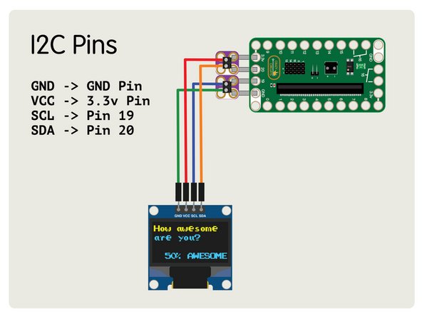
If you are connecting things to the micro:bit which require the I2C bus then you’ll be using Pins 19 and 20.
-
Pin 19 is SCL or “Serial Clock” and Pin 20 is SDA or “Serial Data”. These pins cannot be changed and cannot be used for other purposes.
-
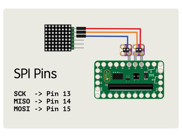
For things that need to connect via SPI Pins 13, 14, and 15 are the default SPI bus. Pin 13 is SCK or “Serial Clock”, Pin 14 is MISO, and Pin 15 is MOSI.
-
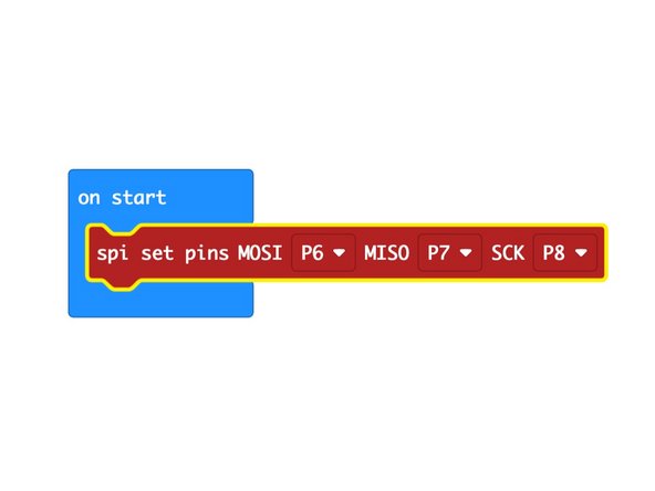
MakeCode allows you to change which pins are used for the SPI bus with a special command if desired.
-
-
-
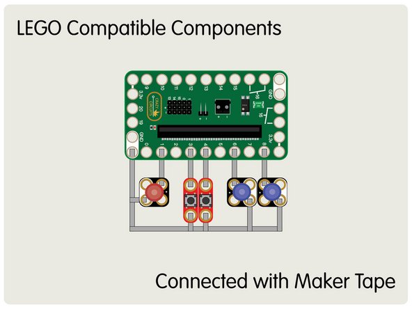
The Crazy Circuits Bit Board “breaks out” most of the pins to be LEGO compatible so you can build circuits with LEGO components and Maker Tape.
-
Without a breakout board like the Bit Board you are very limited in which pins you can use on the micro:bit.
-
Typically Pins 0, 1, 2, and 3V and GND can be connected to with alligator clips, but the other pins are not easily accessible.
-
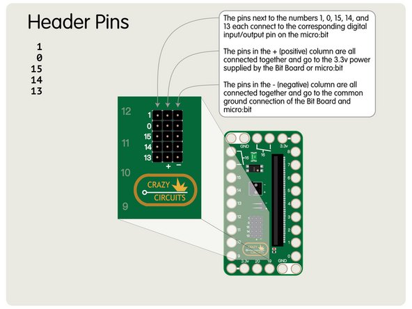
We’ve added a few features to the Bit Board which make It unique. Pins 0, 1, 13, 14, and 15 are also broken out into male pin headers on the Bit Board, with each row also containing a positive and negative pin. These work great for plugging in servos, 7 segment displays, and other sensors and actuators.
-
-
-
As of this writing (February 2021) we noticed a difference between the behavior of the V2 and V1.x micro:bit boards, which is noted below.
-
We’ve used Pin 5 and Pin 11 for some of our projects with an LED connected, and while V1.x of the micro:bit worked perfectly, we noticed that the V2 micro:bit exhibited some strange behavior. (Note: Pin 5 and Pin 11 are connected to the built-in buttons A and B on the micro:bit.)
-
An LED on Pin 5 or 11 will not display at full brightness and will appear to flicker or be a bit dimmer than LEDs attached to other pins. This is a fairly minor issues, but worth mentioning.
-
If using a micro:bit V2 avoid connecting LEDs to Pin 5 or Pin 11. They may not display at full brightness.
-
You can use these two pins with LEDs (they are listed as GPIO Pins) but expect to see them below full brightness when using a micro:bit V2.
-
If you have an LED on Pin 5 or Pin 11 and press Button A or Button B (respectively) you will see your LED turn off as the buttons are also connected to these pins.
-


Hopefully this guide is helpful in understanding the pins on the micro:bit and how to use some of them for specific purposes.
Hopefully this guide is helpful in understanding the pins on the micro:bit and how to use some of them for specific purposes.
Cancel: I did not complete this guide.
One other person completed this guide.
