
Introduction
Do you know what PCB stands for? It stands for "Printed Circuit Board", okay... but what is a Printed Circuit Board? We looked it up and this is what we found: "A PCB mechanically supports and electrically connects electrical or electronic components using conductive tracks". Okay, we can work with that!
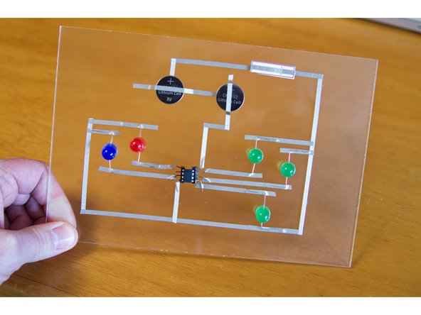
We're going to make a PCB using a "printed" piece of paper and a clear piece of acrylic as the "board" to build our "circuit" on. PCB!
While most paper circuits are simple, we've decided to make ours a bit more advanced. Were going to use an ATtiny85 chip, which is like a very small Arduino. In fact, you can program it using the Arduino software. Ours already had our Blink/ Fade sketch on it.) Our ATtiny85 will allow 5 different LEDs to do 5 different things all at once.
Featured Document
-
-
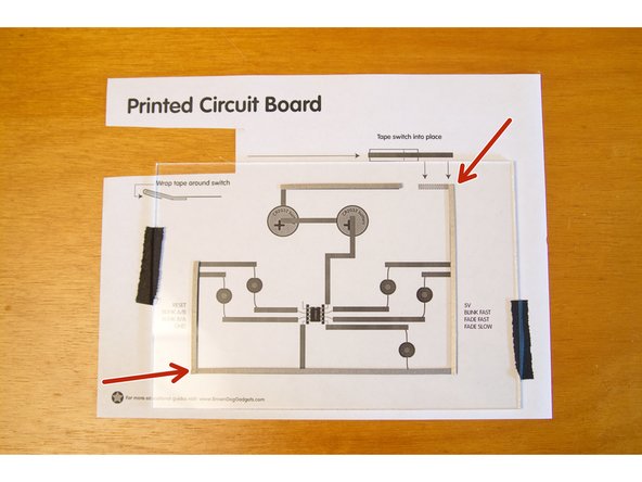
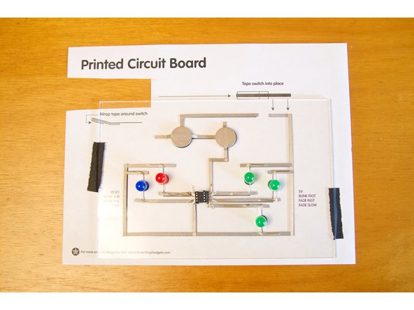
We've provided a PDF that you can print out and place under your clear plastic sheet so you can see your circuit and attach all the components with tape. Make sure your plastic is large enough to fit the entire circuit on.
-
-
-
Every good circuit has a switch. A switch is the thing that completes the circuit and allows the electricity to flow.
-
Without a switch you're either going to have a circuit that never turns on, or a circuit that never turns off. (Both of those are less than ideal.)
-
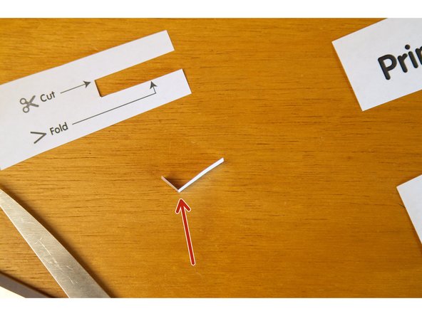
Using a pair of scissors, cut out the switch from your paper print out.
-
-
-
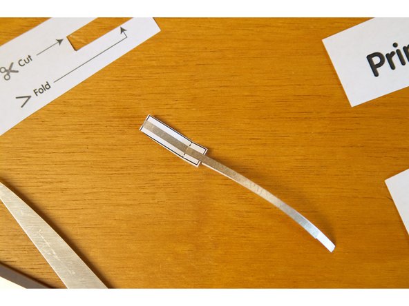
Take your switch and fold it about 90 degrees where indicated with the fold line, and attach a piece of conductive Maker Tape to the switch.
-
When we attach our switch to the circuit it will be activated by pressing down on it so the Maker Tape completes the circuit.
-
Once your switch is assembled you can put it aside, as we won't need it until we get our circuit built.
-
-
-
Pro-tip: It helps to tape the plastic down to the paper!
-
Start using the Maker Tape to trace the circuit you see on the paper. We did the outside of the circuit first as it didn't have any components to attach.
-
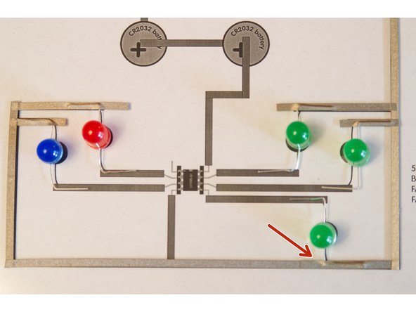
Bend the LED legs to help them stand upright, and so you can run the Maker Tape across a longer portion of the leg for better conductivity and attachment.
-
Oh, you'll notice we forgot that the third green LED should have been put down before the tape on the outer edges... no worries! One of the nice things about Maker Tape is that it's conductive on both sides and all the way through. We can just add a piece of tape to the LED leg and stick it on top of the tape we already applied.
-
Don't forget to make sure you've got your LEDs the right way! The shorter leg is negative (-) and needs to go to the outside of the circuit. The longer leg is positive (+) and needs to face towards the center where the ATtiny85 will go.
-
-
-
While you can just bend up the legs of an ATtiny85 and tape those down, we found that this does a few things... First, it ruins the chip as you won't be able to easily reprogram it or put it into a socket or breadboard, and second, the legs are tiny and the tape has a hard time sticking to them well.
-
Oh, did you program your ATtiny chip yet? You will need a programmed chip! You can find plenty of Instructables that explain how. We've also used SparkFun's TinyAVR Programmer, which makes things pretty easy.
-
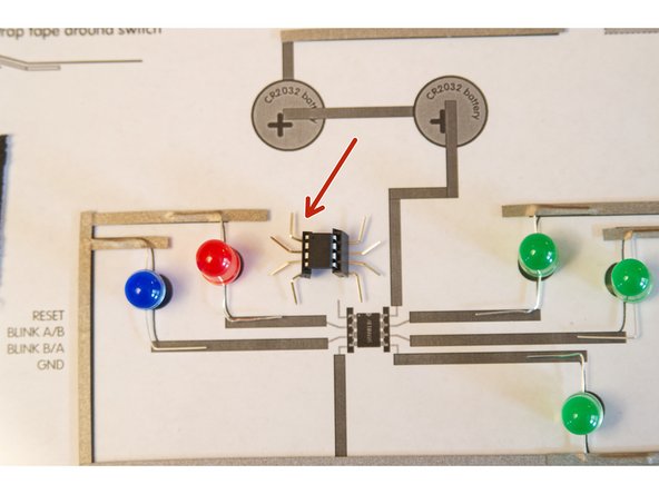
To hold our ATtiny85 we are using what are commonly called "Arduino Stackable Shield Headers" which you can find on Amazon or from a variety of sellers who carry Arduino board. The nice thing about them is that the legs are really long, and we can bend them to our will (and bend them to work in our circuit!)
-
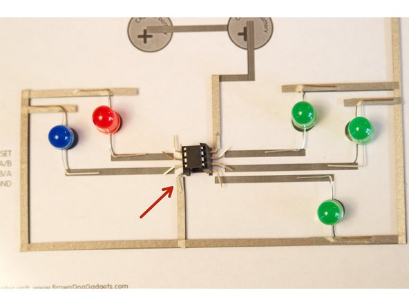
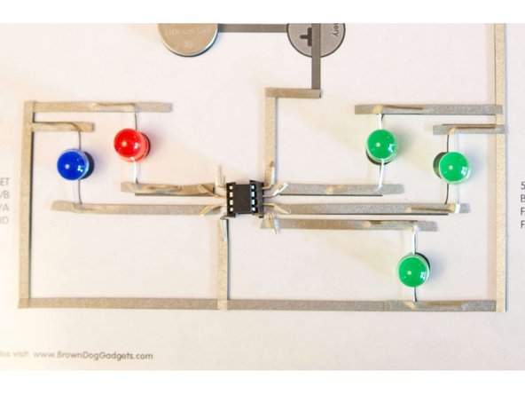
Once you bend the legs and make it look like a little spider, you can add them into the circuit, along with the ATtiny85. Run the tape from the positive LED legs to the pins to make the connections.
-
-
-
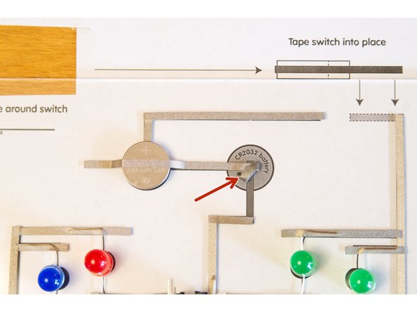
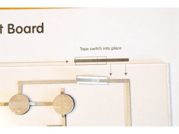
We're going to add two CR2032 batteries to our circuit. Our Maker Tape is going to not only provide the path for electricity from the batteries, but also serve to hold the batteries in place, just as it does with all the other components.
-
Since the tape is conductive all the way through, we can make tape loops to hold the batteries down and serve as a conductor that connects the battery to the "trace" on the board.
-
As we're using two batteries, we've got to connect them somehow, and this circuit connects them in series (versus parallel).
-
When you connect two batteries in series their voltage gets added together, and you get more volts, but the same amount of current. (More current lets your circuit run longer.)
-
If you connect your batteries in parallel you get the same amount of voltage, but more current. Batteries... what can't they do!?!
-
-
-
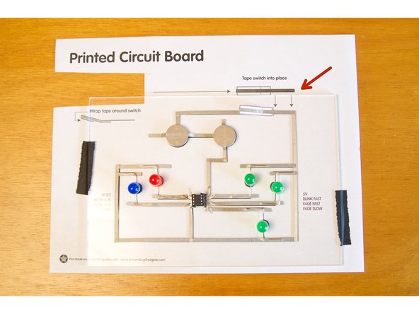
Remember the switch we made? It's time to add it to the circuit!
-
You'll need to tape it down so the "tail" is touching the tape in the upper right corner, and when it folds down it touches the piece of tape across the gap.
-
Interested in switches for paper/tape circuits? We've made a few different ones...
-
-
-
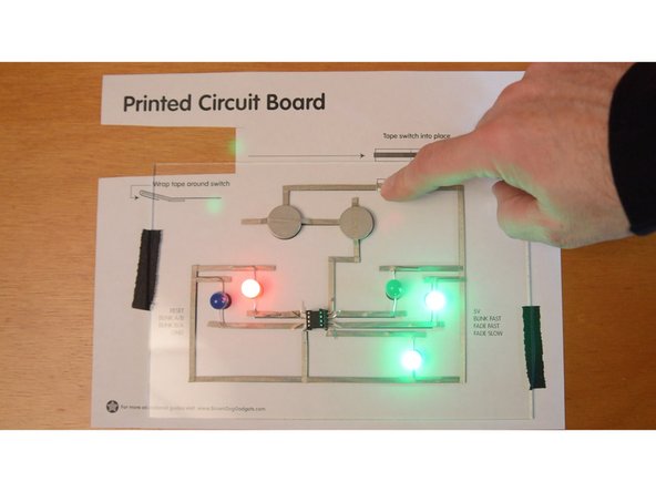
If we did everything right, pressing the switch will complete the circuit and all the LEDs will light up and do crazy things!
-
Feel free to remove the paper and marvel at your "Printed Circuit Board" flashing and blinking like crazy...
-
Since we did this project on clear acrylic you can even flip it around and see the back of the circuit board. Fun fact, most circuit boards have at least two layers, and while ours only has one, it's pretty neat to be able to see it from the bottom view.
-
Did your circuit work? If not, make sure all the tape is pressed down enough to make a good connection. In our initial testing we had one LED that didn't turn on, so we just has to press the tape down a bit more on one of the pins.
-


Cancel: I did not complete this guide.
One other person completed this guide.
Attached Documents
