
Introduction
Creating and scoring games with a micro:bit is simple and easy! In this guide we'll show you several ways to create simple switches and buttons for a DIY Pinball machine, however these same techniques can also be used for all kinds of game creation!
Tools
No tools specified.
Video Overview
-
-
To make obstacles that can score points, we use a metal pinball that acts as a conductor between two pieces of Maker Tape and closes the switch.
-
There are several ways to engineer these switches and incorporate them as obstacles. Read on for three examples in the steps below.
-
-
-
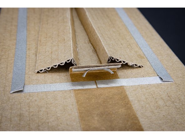
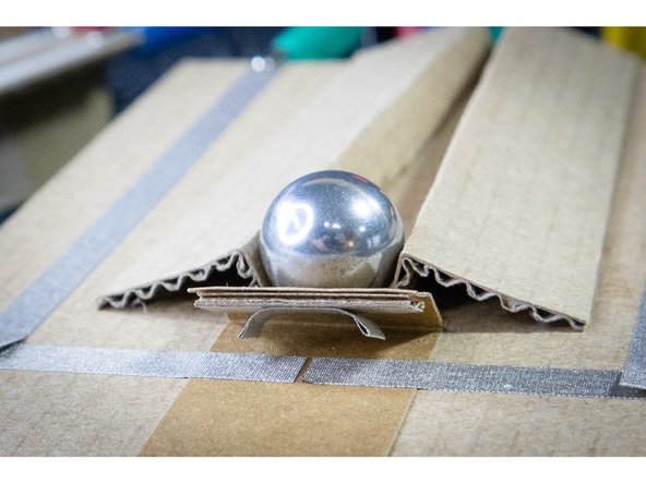
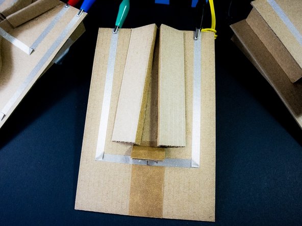
Create a track with two pieces of cardboard glued parallel to each other. They can be straight, or curved as you see in the example.
-
Lay one piece of Maker Tape over one of the tracks, and continue sticking the Maker Tape until it runs over the edge of the cardboard. This will make it easy to clip an alligator clip to it.
-
Repeat with another piece of Maker Tape on the other track, making sure it doesn't touch the first piece.
-
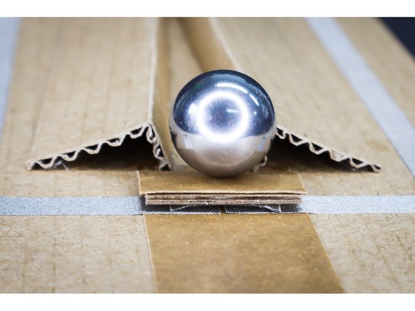
When the ball rolls down the track, it will make a connection between the two pieces and close the switch.
-
-
-
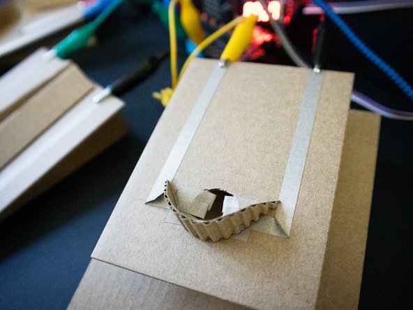
Tape a small rectangle of cardboard to a larger piece to create a flap that looks like a "draw bridge".
-
Fold the ends of a short piece of Maker Tape over so that they don't stick. Stick it underneath the bridge as shown.
-
Run a piece of maker tape to the bridge and leave a gap before continuing.
-
When a ball pushes down the drawbridge, the flaps of Maker Tape will close the gap and connect the switch.
-
-
-
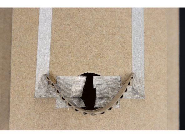
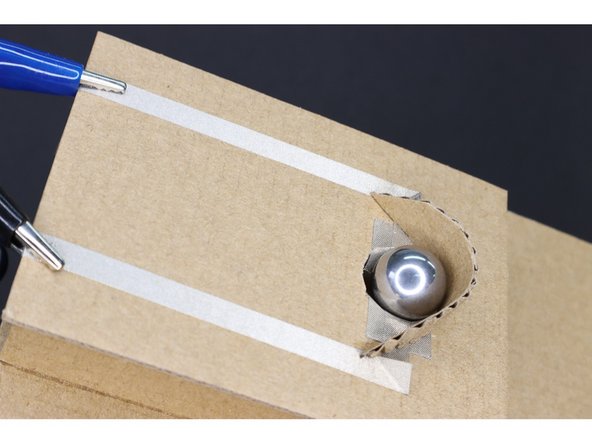
Create a hole in a piece of cardboard that is slightly larger than the ball.
-
Cut 6, 1-inch pieces of Maker Tape, and fold down the first 1/4 inch so that that part doesn't stick.
-
Lay the pieces so the non-sticky part is over the hole, three on each side. The pieces should overlap slightly as well.
-
Run a piece of maker tape to the pieces on one side of the hole, and a second piece of Maker Tape from the other side.
-
Add a cardboard backboard to direct the ball into the hole. When the ball falls through it will brush the Maker Tape and complete the circuit.
-
-
-
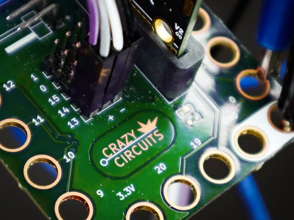
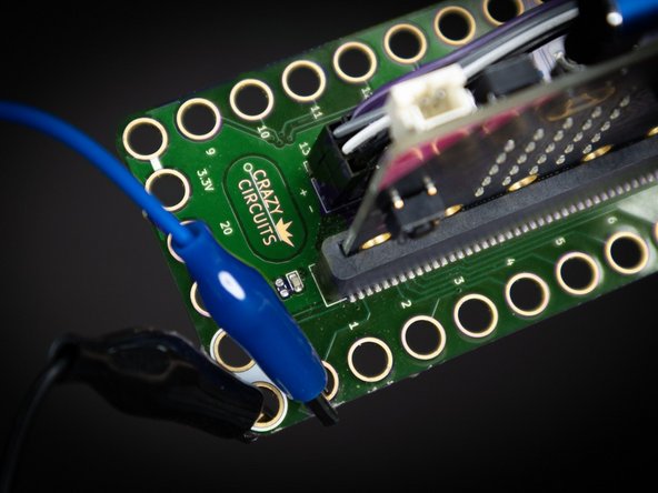
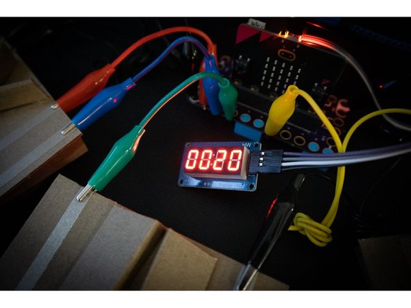
Connect the 7 Segment Display: CLK to Pin 14, DIO to Pin 13, VCC to the + (positive) column, and GND into the - (negative) column.
-
-
-
Using alligator clips, connect one side of each switch to ground, and the other to pin 0, 1, 2, and/or 3. In the example code, we connected all of the switches at once.
-
-
-
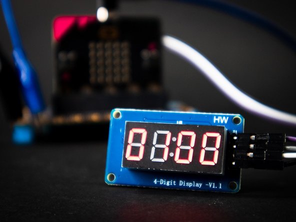
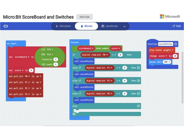
Download the code, available here: Code for micro:bit pinball scoreboard
-
This code will add 10 points to the score every time one of the switches connected to pins 0, 1, 2, or 3 are pressed. If you'd like to reset the score, simply press the reset button on the back of the micro:bit.
-
-
-
Now that you have the basics, it's time to make your own electronic pinball game!
-
For inspiration, check out this PinBox 3000 game that incorporates our Bit Board : https://youtu.be/N-xYRhL5_3o
-


Cancel: I did not complete this guide.
One other person completed this guide.
