
Video Overview
Featured Document
-
-
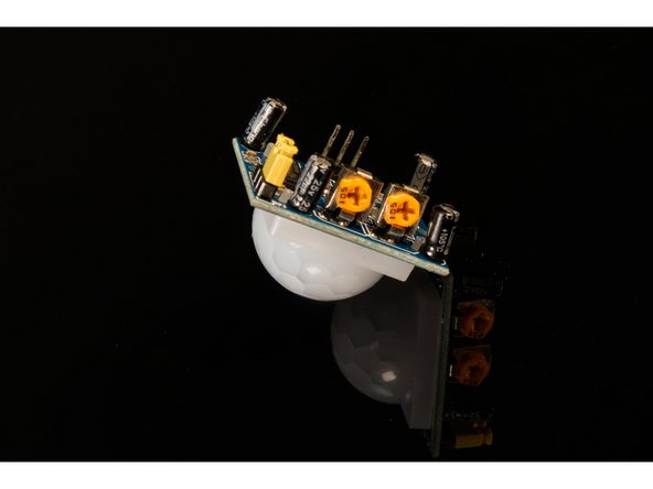
A Pyroelectric (or "Passive") InfraRed sensor works by detecting infrared radiation, which we commonly refer to as heat. When a person (or animal) passes in front of a PIR sensor it can detect the difference from the ambient heat in the space in front of it and “detects” that a living creature is in view.
-
You’ve probably seen spotlights on a house or garage that turn on when a person or animal walks in front of them. They use PIR sensors. They are often called “motion sensor lights” though they will only detect motion from an object that radiates enough heat to cause a difference in heat from the environment.
-
There are a few ways to adjust the output from the sensor, but you make those adjustments on the sensor itself, not in the code.
-
-
-
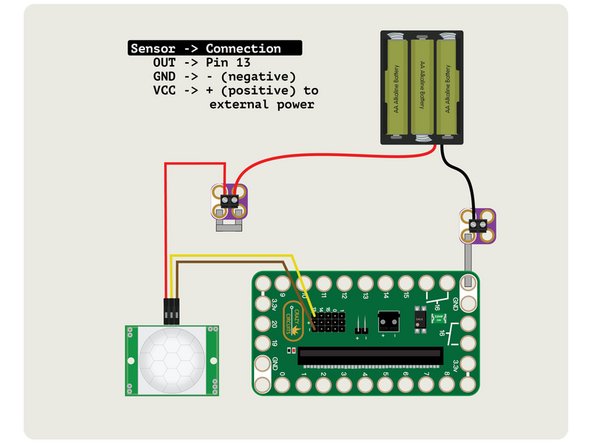
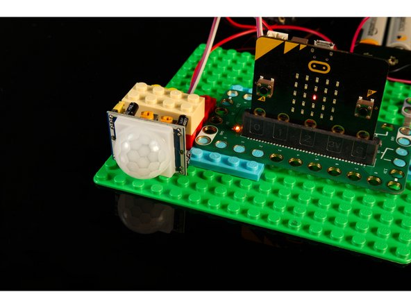
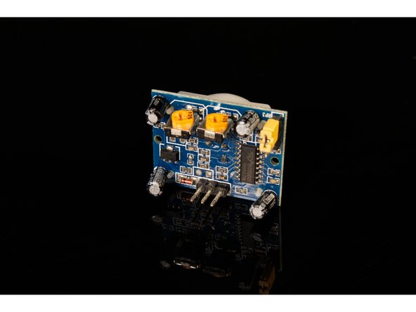
The PIR sensor is very simple to connect, with just three wires, and puts out a LOW signal when nothing is detected and a HIGH signal when something is detected.
-
Note: You may need to remove the white plastic lens on the front of the sensor to check which pin is which if it is not labeled on the back of the sensor.
-
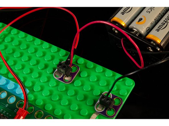
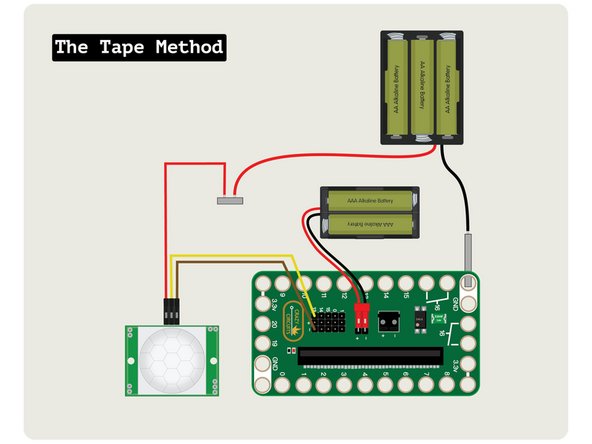
Using a F/F Jumper Wire connect OUT from the sensor to Pin 13 on the Bit Board.
-
Using another F/F Jumper Wire connect the GND on the sensor to one of the - (negative) pins on the Bit Board.
-
Next use a F/M Jumper wire and connect the Female side to the VCC pin on the sensor. Don't connect the other end to anything yet...
-
-
-
The PIR Sensor we used requires more than the 3 volts supplied by the micro:bit to work properly, so we're going to power it externally.
-
Check your sensor! If you have one that can be powered by 3 volts you can plug it directly into the micro:bit for power. Most of the PIR Sensors we found need at least 4.5 volts.
-
We've connected the VCC from the sensor to one side of a Crazy Circuits Screw Terminal Chip, then connected our 3 AA Battery Pack positive wire to the other side. We've "shorted" the chip with a piece of Maker Tape so the two wires can connect.
-
Notice that the 3 AA Battery Pack positive power wire goes only to the PIR Sensor. It will power the sensor, and nothing else in our circuit.
-
If you don't have any Crazy Circuits Screw Terminal Chips we'll show you an alternative connection method in Step 6.
-
-
-
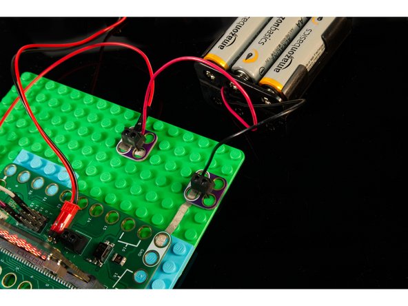
We're going to connect the negative wire from our AA Battery Pack to another Crazy Circuits Screw Terminal Chip and then connect that to GND on the Bit Board using Maker Tape.
-
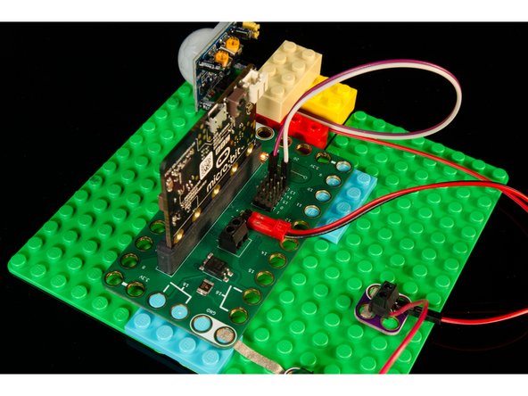
We've now got power flowing to our PIR Sensor! We're not done yet though... we still need to power our Bit Board and micro:bit
-
In almost all cases where you are using more than one power supply, the grounds should all be connected together. Failure to do so can cause your circuit to function in peculiar ways, or not work at all.
-
-
-
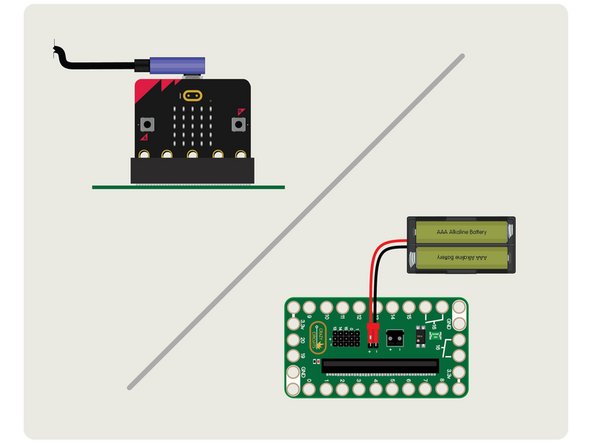
We can provide power to the micro:bit and Bit Board by using a USB cable (which we'll need for programming the micro:bit in the next step) or by using a 2 AAA Battery Pack.
-
The USB cable provides 5 volt power from a computer or USB wall adapter or battery pack, and the voltage regulator on the micro;bit drops the 5 volts down to 3 volts to provide power.
-
A battery pack with two AAA batteries provides just over 3 volts when using two fresh alkaline batteries. This also helps if you want your project to be a bit more portable.
-
Hey, it doesn't work! We've got our power, but we still need to load the code.
-
-
-
We used two Crazy Circuits Screw Terminal Chips to connect our 3 AA Battery Pack to the sensor and to the Bit Board, but there's more than one way to connect a circuit!
-
For the positive wire we could try to twist the wires together, though in the case of Jumper Wires you may need to wrap the other wire around it. (Make sure you insulate them with some non-conductive tape if you use this method.)
-
You can also just tape the two positive wires down with some conductive Maker Tape. As long as they overlap and/or the tape touches both wires it should be a good connection. Tape it down to something non-conductive like a LEGO baseplate.
-
For the negative wire of the battery pack you can probably tape it directly down to your LEGO baseplate and then run the tape to one of the GND holes on the Bit Board. Check out the guide on using Tape to Wire Connections to see how it's done.
-
-
-
Connect a USB cable to the micro:bit and then plug it into your computer.
-
We'll be using makecode.microbit.org to program our board. It uses a simple drag and drop block interface.
-
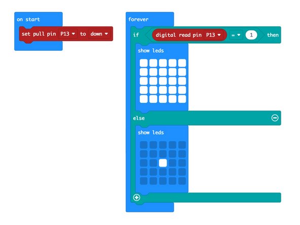
We're going to load the following code for our PIR Sensor program: https://makecode.microbit.org/_bvgEHPcRa...
-
The code is very simple. The PIR Sensor puts out a LOW signal when nothing is detected, and a HIGH signal when something (a person, animal, or something producing heat) is detected.
-
We're going to turn on a single LED on the front of the micro:bit when nothing is detected, and turn them all on when something is detected.
-
-
-
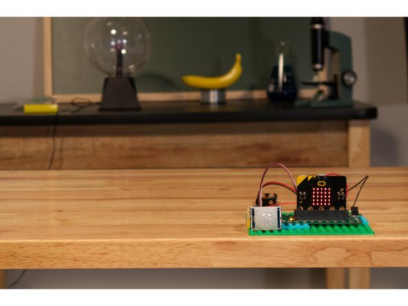
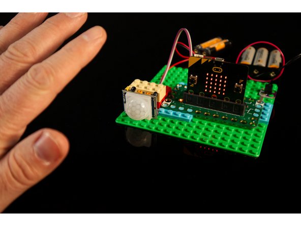
If you've built this project on your desk and the PIR Sensor is pointing right at you it may trigger immediately. You've been detected!
-
You'll want the PIR Sensor pointing in a direction where there is some open area. It can sit on the edge of your desk pointing towards the room your in, though it's best if no other people (or animals) are in the room when you test it in Step 9.
-
-
-
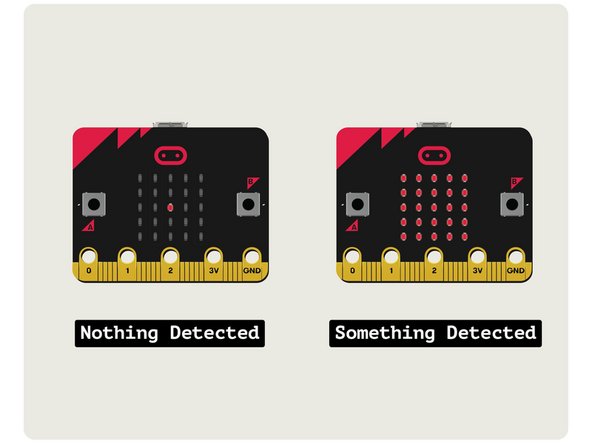
Time to test it out! If possible, leave the room, and then as you enter the room and walk into the view of the sensor it should detect you and change from one LED lit to showing all of the LEDs lit.
-
Try standing completely still once you are detected. Does it reset to a single LED as though you are not there? Now move! Did it see you?
-
Because the sensor looks for a difference in infrared radiation ("heat") you need to be moving to be detected. If you've ever used a hand dryer that you wave your hand under, it's a combination of motion and heat that is being detected.
-
What if your cat or dog runs into the room? Does the PIR Sensor detect them?
-
-
-
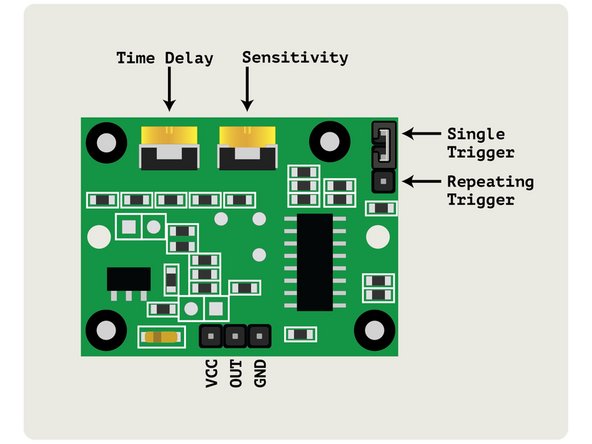
There are a few adjustments you can make to the sensor. These are detailed in the attached PDF file for this guide.
-
We found that the best settings for the PIR sensor we used was to set the Time Delay and Sensitivity potentiometers all the way down (counterclockwise) and to have the jumper set to Single Trigger.
-
Feel free to play around with the settings to see if you get different results.
-


Cancel: I did not complete this guide.
One other person completed this guide.
Attached Documents
