
Introduction
Use our Robotics Board to build a robot that can move in a unique way.
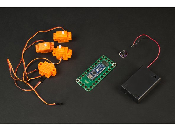
Parts
- Crazy Circuits Robotics Board
- Brick Compatible 360 Degree Servo × 4
- Omni Wheels × 4
- LEGO Baseplate 32 x 32 (2836 / 3811)
- LEGO Technic Brick 1 x 6 with Holes (3894) × 4
- LEGO Plate 2 x 4 (3020) × 16
- LEGO Axle 8 (3707) × 4
- LEGO Axle Connector (Smooth with ‘x’ Hole) (59443) × 4
- LEGO Brick 2 x 2 (3003 / 6223) × 8
- LEGO Bracket 2 x 2 - 2 x 2 Up (3956 / 35262) × 8
- Misc LEGO Parts
- 3 AA Battery Holder
- Crazy Circuits Screw Terminal Chip
- Maker Tape
Video Overview
Featured Document
-
-
Omni Wheels (sometimes called "Poly Wheels") are a type of wheel with small rollers around the circumference which are perpendicular to the turning direction.
-
An Omni Wheel can be driven as a normal wheel can, but the rollers allow for sliding laterally with ease.
-
In the image you can see the red arrows indicating the normal direction a wheel can roll, and the blue arrows showing the sideways movement that is possible.
-
Omni Wheels are interesting because a robot that uses them doesn't need to "turn around" to face a specific direction before moving, it can just move in that direction.
-
-
-
Often robots use three or four wheels, with just two wheel driven, and the others being support wheels. (Our Obstacle Avoiding Robot comes to mind.)
-
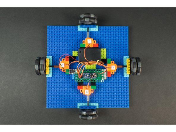
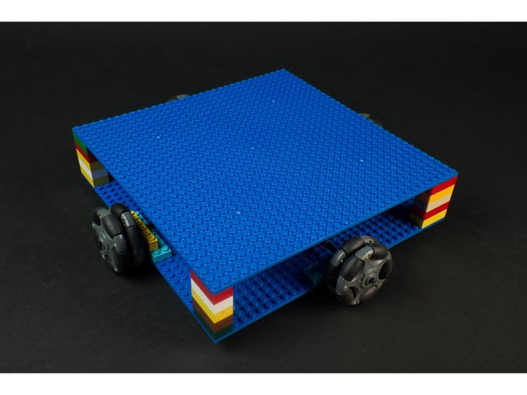
Our Omni Wheel Robot uses all four wheels to drive it, and depending on which wheels are driven, and in which direction, we can move our robot in different directions.
-
Our robot can go forwards and backwards (as most robots can) but it can also move diagonally without having to rotate and orient itself to face the direction of movement.
-
Think of this robot as the Queen in a game of chess. It can move forward, backward, left, right, or any of the four different 45 degree angles.
-
Our robot can also easily spin around in place, either clockwise or counter-clockwise by running all the motors the same direction at the same time.
-
-
-
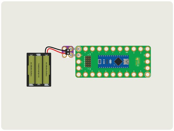
We're going to use our Robotics Board, along with 4 LEGO Compatible 360 Degree Servos, and power it with a 3 AA Battery Pack. (We'll use a Screw Terminal Chip to connect the power to the board.)
-
Most robots use stepper motors which allow for more precise movement, and often use encoders to track the rotation of each wheel. Our robot will be much simpler, which makes it a good beginner project.
-
-
-
The LEGO parts we used are all listed under the Parts section of the Introduction to this guide. We'll cover them in detail here.
-
We'll use a LEGO Baseplate (32 x 32) as our build platform. It provides enough room to mount the four motors, and has space for the Robotics Board and Battery Pack.
-
The Robotics Board itself will just attach to a few LEGO bricks, as will the Screw Terminal to provide a simple power connection. A few more bricks can be used to hold our Battery Pack in place.
-
The servo motors will mount using the right angle LEGO Bracket 2 x 2 - 2 x 2 Up. (This is a part you may not have handy but it's the best part we found for this application.) We'll use 8 of them, along with 8 LEGO 2 x 2 Bricks for our servos.
-
Each servo and motor pair will be connected using a LEGO Axle and a LEGO Axle Connector with a LEGO Technic Brick with Holes for axle support on top of a set of doubled-up LEGO Plates.
-
While we've listed specific parts, if you are familiar with LEGO you'll know that substitution is possible in many cases. While we listed the LEGO Technic Brick 1 x 6 with Holes you could use a shorter or longer brick, as long as it has the needed holes. Or, for instance, if your axles are slightly longer it shouldn't make much difference.
-
-
-
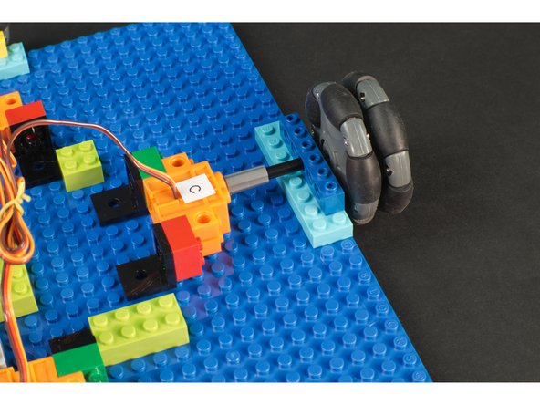
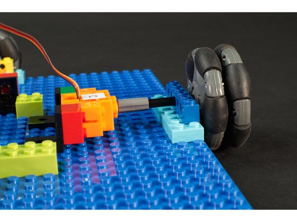
The servos will be mounted on their sides, with the wires on the top side. They are held in place by 2 x 2 bricks attached to the servos, and then the 90 degree LEGO bracket attached to the bricks.
-
If this isn't enough to secure your servos in place you can add more bricks and brackets.
-
The shaft of the servo has a LEGO axle connector attached, and then a LEGO Axle connected to it and the omni wheel. It goes through a Technic brick with holes sitting atop a stack of two LEGO plates.
-
This combination worked for us to get the servo secured in place and connected to the wheel. Feel free to use other methods depending on the parts you have available. The important thing is to mount the assembly so the wheels are centered and the servos are held in place.
-
-
-
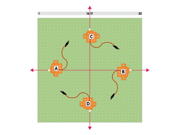
With our 32 x 32 LEGO Baseplate we'll need to mount each servo so it is centered on the plate. Specifically, so the shaft of each servo is centered on the plate.
-
If you count from any corner you'll find that between the 16th and 17th LEGO stud is the center point, so align your servo so the shaft is between those two studs.
-
You'll notice we've labeled our four servos A, B, C, and D. This will be helpful later on when we program things. (We'll consider C the front, D the back, and A the left and B the right.)
-
-
-
Once you know the position of each wheel assembly you can mount the servos to the LEGO Baseplate.
-
The great thing about LEGO? If you don't get it right the first time it's easy to move things around!
-
-
-
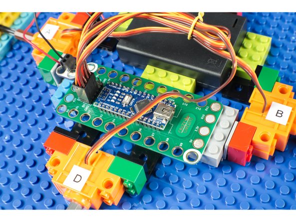
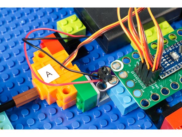
Each servo connector has three wires. The orange wire is the signal wire, and goes into the labeled pin. (For Servo A that is Pin D3.) The red wire then goes to the 5V row, and the brown wire goes to the GND row. This powers the servo and allows the Robotics board to send signals to control it.
-
Connect Servo A to D3, Servo B to D5, Servo C to D6, and Servo D to D9.
-
-
-
We just stuck the Robotics Board down to a few LEGO bricks to mount it to our robot.
-
Since we need to add the Screw Terminal Chip this worked out well.
-
-
-
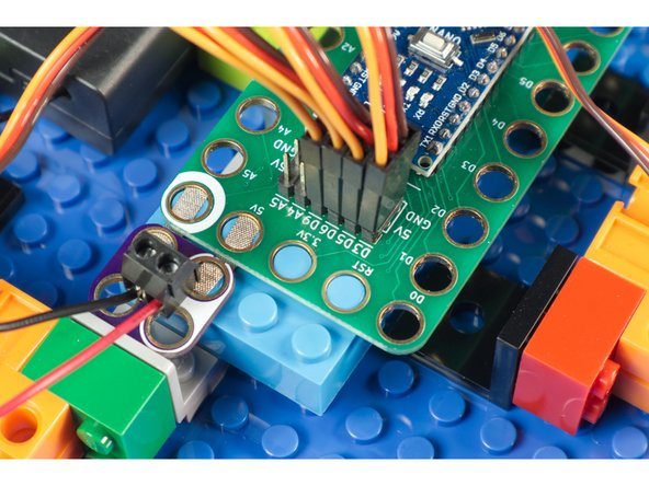
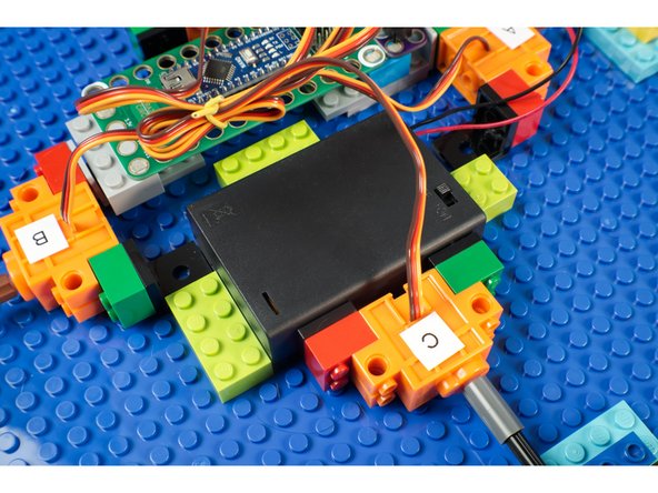
To power our robot we used a Crazy Circuits Screw Terminal Chip and two short pieces of 1/8" Maker Tape to connect the Battery Pack to the Robotics Board.
-
The Robotics Board power input is for 5 volts. Our Battery Pack should provide 4.5 volts with a set of fresh AA Alkaline batteries, which will work fine.
-
We used a few LEGO Bricks stuck down to the LEGO Baseplate to keep our Battery Pack in place and prevent it from sliding around while the robot is moving.
-
-
-
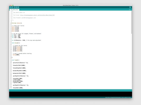
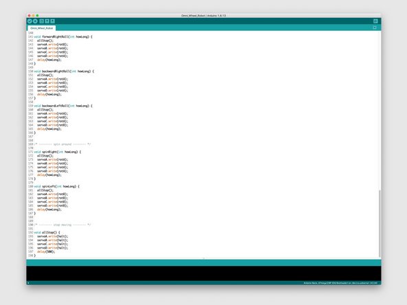
Before our project will work you'll need to upload code to the Robotics Board. If you've not done so already, make sure you have the latest version of the free Arduino IDE software installed on your computer.
-
The code can be found at our GitHub repo, which you can find here: https://github.com/BrownDogGadgets/Crazy...
-
The code has been commented to help explain what everything does.
-
-
-
Once your robot is built, programmed, and powered... you can test it out!
-
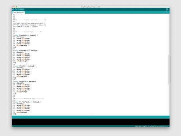
If you didn't change the code at all it will go through all of the movements it is capable of doing.
-
Each movement is a function in the code, and you call it with the number of milliseconds you want it to run for. (Remember 1000 milliseconds = 1 second.)
-
-
-
Now that you've got a rolling platform, maybe you want to build on top of it!
-
Maybe you want to build a mobile dance floor for your Minifigs.
-
Adding a top plate might make it difficult to reach the battery pack, though you can easily remove the top plate to access it.
-
You could add a Crazy Circuits Slide Switch along the edge of the Baseplate with some Maker Tape running between the battery and Robotics Board for an easy to access power switch.
-
You could even build an entire Crazy Circuits project on top and take it for a spin!
-
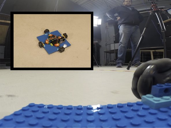
We mounted a GoPro camera on ours and let it go crazy in our studio.
-


Cancel: I did not complete this guide.
One other person completed this guide.
Attached Documents
