
Introduction
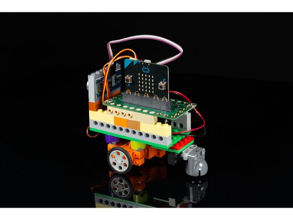
Build a simple LEGO-based obstacle avoiding robot using two 360 degree continuous rotation servos, a distance sensor, and a Crazy Circuits Bit Board & micro:bit.
Parts
- Crazy Circuits Bit Board
- micro:bit
- Distance Sensor
- Brick Compatible 360 Degree Servo × 2
- Jumper Wires × 4
- 2 AAA Battery Holder
- LEGO Wedge Belt Wheel (4185 / 49750) × 2
- LEGO EV3 Technic Ball Pivots Set 5003245
- LEGO Technic Cross Block Beam 3 with Four Pins (48989 / 65489)
- LEGO Technic Brick 1 x 6 with Holes (3894)
- LEGO Axle 4 with End Stop (87083) × 4
- LEGO Half Bushing (32123 / 42136) × 4
- LEGO Brick 2 x 2 Round (3941 / 6143) × 4
- LEGO Plate 6 x 12 (3028)
Video Overview
Featured Document
-
-
A few notes before we get started...
-
We also have a version of this project that works with our Robotics Board. Check out Obstacle Avoiding Robot (Robotics Board). The only real difference is which board we use for controlling the robot.
-
We used a variety of LEGO parts but you should feel free to build yours however you see fit, using whatever parts you have on-hand. The important things you’ll need to do is have a way to mount the servos on the bottom, the ultrasonic sensor so it can point to the front, and some way to hold the Robotics Board and power source in place.
-
In a pinch you can use some tape or rubber bands to mount things where needed. We have provided links to each part on BrickOwl but you can find them anywhere LEGO or LEGO-compatible parts are sold.
-
-
-
We started with a 6 x 12 LEGO Base, which was the smallest we were able to build with. (It also matches the width of the Bit Board.) You can go larger if desired but smaller may be a challenge.
-
Make your base tall enough to accommodate the 2 AAA battery pack and leave room above it to fit the Bit Board.
-
-
-
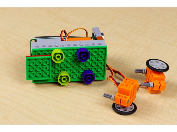
Each servo motor will need to get mounted to the bottom of your robot base.
-
We ended up using these parts to do so:
-
LEGO Axle 4 with End Stop (87083)
-
LEGO Half Bushing (32123 / 42136)
-
LEGO Brick 2 x 2 Round (3941 / 6143)
-
You'll need 4 of each part to mount the 2 servos.
-
Once mounted you can add the wheel, which is LEGO Wedge Belt Wheel (4185 / 49750).
-
We found that if we offset the servos by one stud the wheels line up a little better since the servos are rotated opposite each other in respect to where the wheel is positioned.
-
-
-
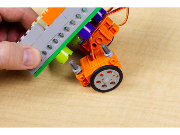
Push the axles attached to the servos flush up to the round LEGO pieces.
-
Once you've got both wheels in place you're ready for the third wheel!
-
Like other LEGO builds, there are many options! This servo/wheel mount is what worked for us, but you can try something different.
-
-
-
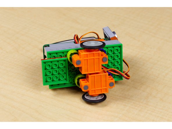
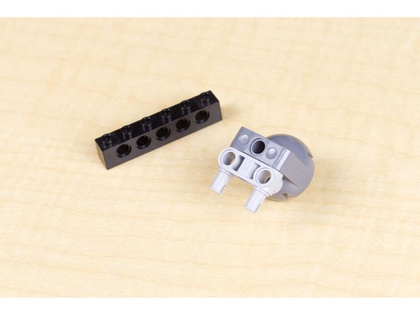
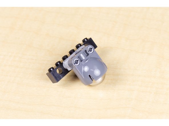
Our caster wheel allows our robot to roll, powered by the two wheels attached to the servos, with the caster acting as the "third wheel" so our robot can pivot and move easily.
-
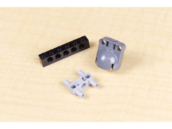
These are the parts we used for our caster wheel attachment:
-
LEGO EV3 Technic Ball Pivots Set 5003245
-
LEGO Technic Cross Block Beam 3 with Four Pins (48989 / 65489)
-
LEGO Technic Brick 1 x 6 with Holes (3894)
-
-
-
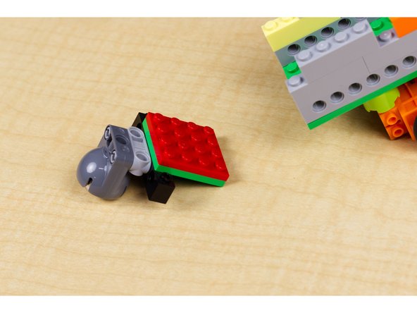
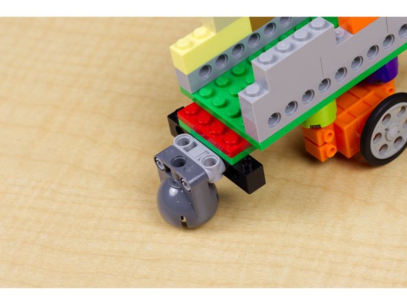
Attach caster wheel to back of robot adding any needed bricks. (We used two thin LEGO plates.)
-
In an earlier version of our robot we just used a few round LEGO pieces as a "leg" and those work fine on a smooth surface like a table, but do not work well on carpeting or a non-smooth floor. If you don't have a caster wheel handy, consider the "leg" option.
-
-
-
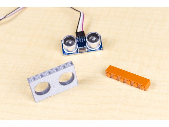
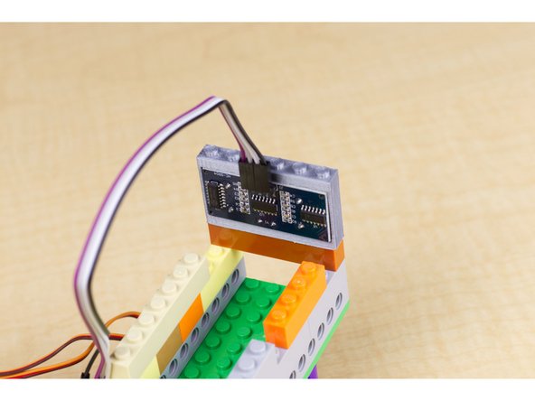
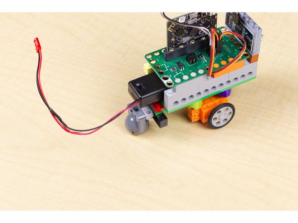
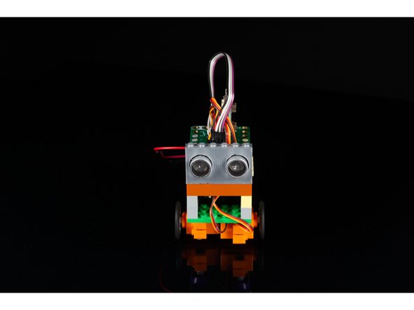
We'll want to mount the ultrasonic distance sensor on the front of the robot so it can "see" where it is going, and know when to stop before hitting an obstacle.
-
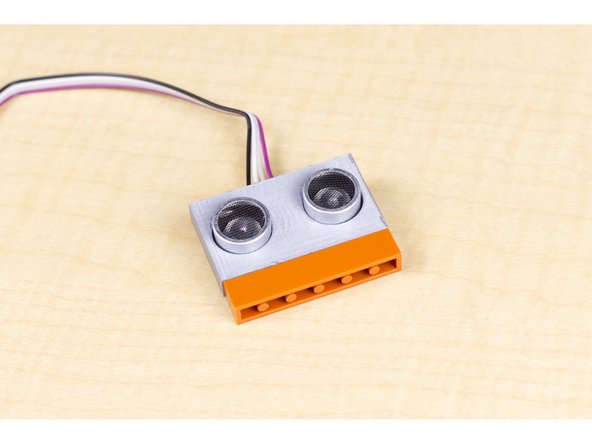
We 3D printed a LEGO-compatible holder for the ultrasonic sensor. You can find the file on Thingiverse if you want to use it: https://www.thingiverse.com/thing:317100...
-
If you do not have access to a 3D printer, you can fashion a way of holding the sensor in place using some LEGO pieces, tape, rubber bands, zip ties, or some other method. The important thing is that it should point towards where the robot is going when it is moving forward.
-
-
-
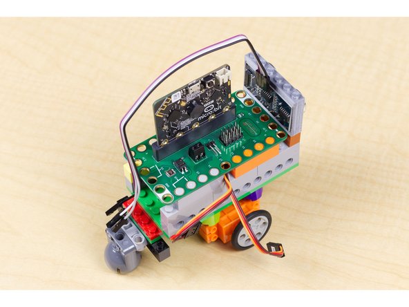
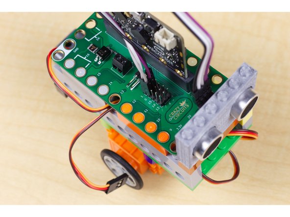
The Bit Board holds the micro:bit, which is the brains of this operation. The Bit Board is meant to sit on top of LEGO bricks so mounting it is simple.
-
Typically the Bit Board is use with conductive tape to build circuits directly on top of LEGOs, but since we're just using two servos and a distance sensor, we can plug those directly into the header pins on the board.
-
Next we'll plug in the sensor and the servos!
-
-
-
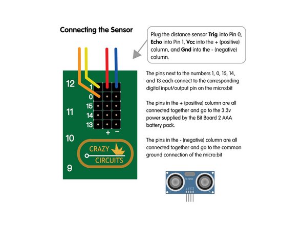
For the sensor you'll need to connect the trigger pin to Pin 0 on the Bit Board, then connect the echo pin to Pin 1. Next connect VCC to any pin in the + column and Gnd to any pin in the - column. This will power the sensor and allow it to talk to the micro:bit through the Bit Board.
-
-
-
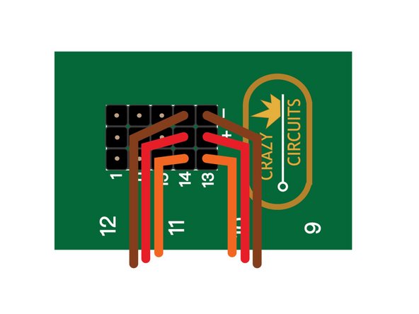
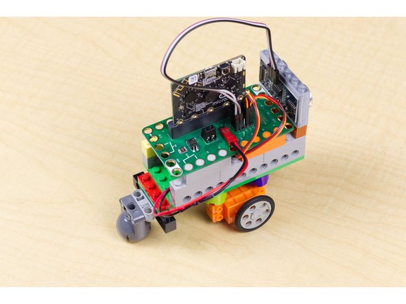
Next you'll need to attach each servo connector. They are easy to plug in, just make sure that the brown wires connect to pins in the - column, the red wires connect to pins in the + column, and the orange wires connect to pin 13 for for left servo, and 14 for the right servo.
-
-
-
Connect a USB cable to the micro:bit and then plug it into your computer.
-
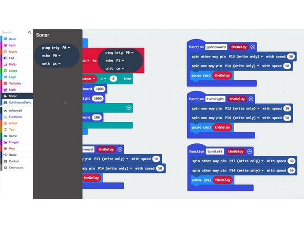
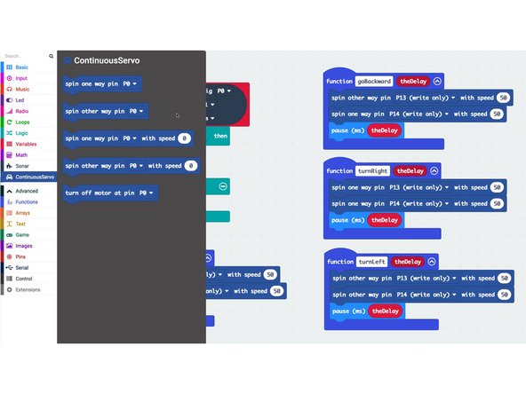
We'll be using makecode.microbit.org to program our board. It uses a simple drag and drop block interface.
-
We're going to load the following code for our Obstacle Avoidance Robot program: https://makecode.microbit.org/_UCY8Ld9vY...
-
You can change the code to affect how the robot moves. There are four "functions" in the code, goForward, goBackward, turnLeft, and turnRight.
-
We're calling the turnRight function but you could change the code to call the turnLeft function instead.
-
Remember, 1000 milliseconds is equal to 1 second, 5000 milliseconds is equal to 5 seconds, etc.
-
Once the code is loaded you can disconnect the USB cable and insert the micro:bit into the Bit Board so it can control the servos.
-
We are using two "Extensions" in our code. One for the sensor (called Sonar) and one for the servos (called ContinuousServo). MakeCode will automatically load these if you use the link to our code above.
-
-
-
Once you've got your robot built, and the code has been uploaded to the micro:bit you can test it out!
-
Plug the battery pack into the Bit Board and your robot should start rolling. If you put your hand in front of the sensor, it should back up, turn, and then move forward again. (Don't let it roll off of a table!)
-
We built a simple hexagonal cardboard "arena" for our robot to roll around in using an old cardboard box. Feel free to get creative with what you have on hand.
-
-
-
Below are some questions and an additional activity if you want to go a bit further with this project.
-
What did you learn when building your robot?
-
What determined your choices in LEGO parts used?
-
Would your robot roll faster or slower if it had larger wheels?
-
What if you offset the wheels my changing where they attach to the baseplate?
-
What if you spread the wheels further apart by adding more LEGO pieces?
-
There are two variables in the code you can adjust that will change the amount of time the robot runs when it backs up and then turns to avoid a wall. Feel free to change the numbers used when a function is called. Don't forget to re-upload the code if you change it.
-


Attached Documents
