
Introduction
Learn how to use the LEGO Compatible 270 Degree Servo with a micro:bit and how to set the correct angle.
Video Overview
Featured Document
-
-
Servo Motors are a type of actuator that can be controlled to rotate a shaft to a specific angle. This is different than a typical motor which spins a shaft 360 degrees clockwise or counterclockwise.
-
While there are very precise (and very expensive) industrial servo motors used to control large machinery, we’ll be focusing on “Hobby” or “RC” servos, which can be controlled with a microcontroller like the micro:bit or an Arduino.
-
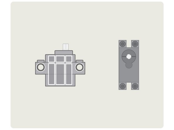
This guide will focus specifically on the LEGO Compatible 270 Degree Servo.
-
-
-
If you remember our Xylophone project you'll know why the angles are so important.
-
We needed to determine the angle for the arm servo so it could move left and right to position the mallet over the correct bar...
-
And we needed to determine the angle for the mallet servo so it could move down to strike the bar and then back up into the resting position.
-
For most projects that use servos you'll need to determine the angles so your servo can move between two or more positions, and there is often a lot of testing involved to get it just right.
-
Hopefully this guide will give you the basics of getting the LEGO Compatible 270 Degree Servo with MakeCode to do what you want!
-
-
-
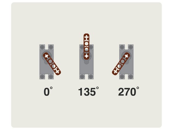
The LEGO Compatible 270 Degree Servo can move the shaft between 0 and 270 degrees, approximately.
-
As we're working with what are considered "hobby" servos, they are not super-precise. In fact, you may have a servo that moves from 0 degrees to 280 degrees or more.
-
The important thing is learning how to make it move, and then knowing how to change and adjust the movement to work for your project.
-
-
-
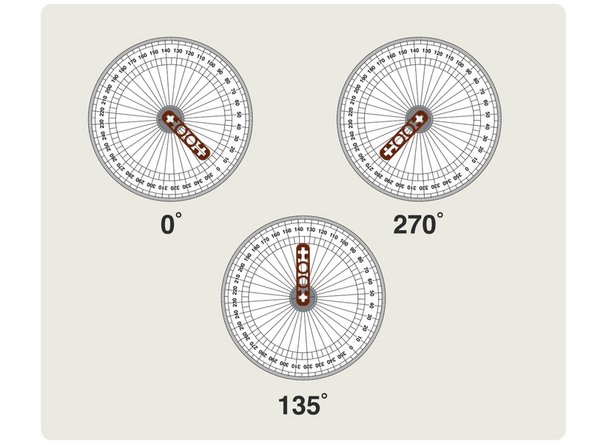
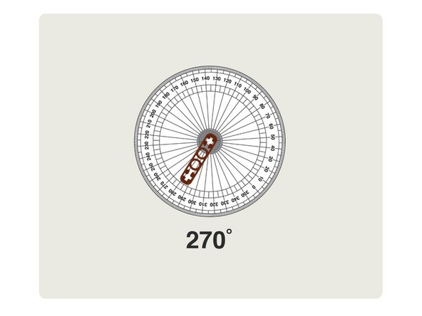
We've included a PDF that is sized appropriately for you to print, cut out, and place over a servo to function as a guide to show the angles.
-
-
-
We're going to place our paper guide on our 270 degree servo.
-
When we set the servo to 0 degrees we can then rotate the guide into place so it lines up the zero with the LEGO beam.
-
Then when we move the servo we can check the angle it is pointing at.
-
-
-
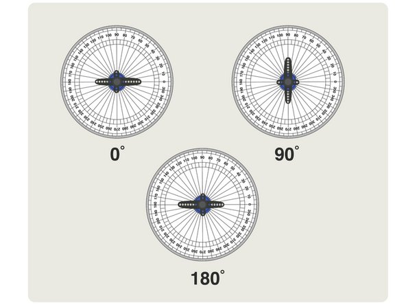
If you've used other hobby servos that were listed as "180 Degree Servos" they would act as expected, and move from 0 degrees to 180 degrees.
-
We're going to focus on the LEGO Compatible 270 Degree Servo in this guide, but we will reference a standard 180 Degree Servo for comparison.
-
-
-
As of this writing, our favorite code editor for the micro:bit (makecode.microbit.org) supports controlling servo angles from 0 degrees to 270 degrees, with some caveats...
-
While the servo value slider control only goes to 180, you can type in values above 180 (say, 270 for instance.) The range of the servo is mapped to the values between 0 and 180...
-
This means if you set your servo to 180 it will actually move to 270 degrees, and if you set it to 90 degrees (halfway for a 180 degree servo) it will move our 270 degree servo to 135 degrees.
-
Luckily it's fairly easy to do the needed math to convert 0-180 to 0-270 when writing code.
-
-
-
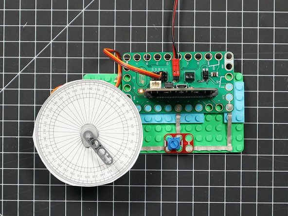
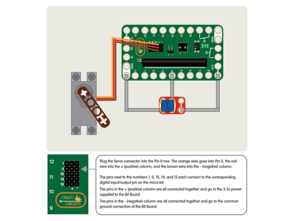
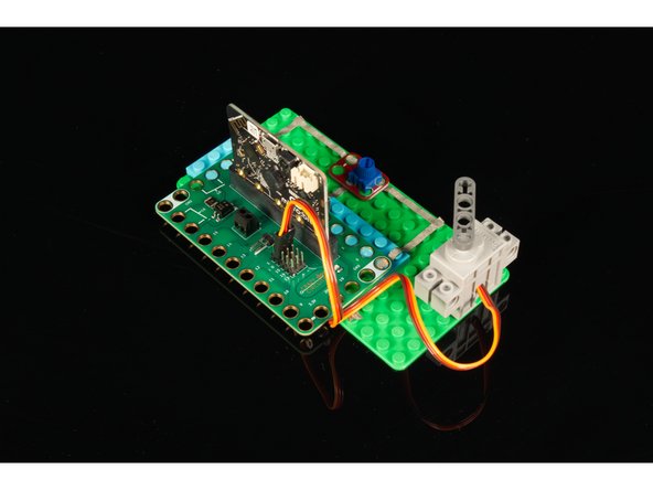
Let's build our circuit! We're going to connect the servo to the header pins on the back of the Bit Board. (It may be easier to do this before you insert the micro:bit)
-
We recommend plugging in the servo when your Bit Board and micro:bit do not have power. So if your micro:bit is inserted into the Bit Board make sure the USB cable is not connected and the battery pack is not powered on.
-
Plug the Servo connector into the Pin 0 row. The orange wire goes into Pin 0, the red wire into the + (positive) column, and the brown wire into the - (negative) column.
-
The pins next to the numbers 1, 0, 15, 14, and 13 each connect to the corresponding digital input/output pin on the micro:bit
-
The pins in the + (positive) column are all connected together and go to the 3.3v power supplied to the Bit Board.
-
The pins in the - (negative) column are all connected together and go to the common ground connection of the Bit Board.
-
Add the Crazy Circuits Potentiometer as shown. The center of the potentiometer should go to Pin 4 on the Bit Board and then one side will go to GND (Ground) and one side will go to 3.3v
-
Make note of the orientation of the potentiometer. If it is rotated 180 degrees your servo will go clockwise when it should go counterclockwise and vice versa. If this happens just remove it, rotate it, and put it back in place.
-
-
-
When using a servo we recommend powering your circuit with a 2 AAA Battery Pack.
-
If you are using a micro:bit V2 you may be able power one servo with just a USB cable plugged into the micro:bit, but adding any more components may require more power.
-
If you are using a micro:bit V1 you will definitely need to use a 2 AA Battery Pack to power the servo. If you try to power it from USB you'll hear a faint clicking sound and the servo will not move.
-
To ensure your servos operate properly when connected to the Bit Board the recommended best practice is to add a 2 AAA Battery pack.
-
-
-
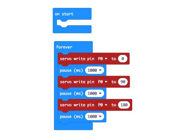
Here's our first code example, LC270 Servo 1: https://makecode.microbit.org/_Voud90hpf...
-
Load this code onto your micro:bit and examine the behavior. Your servo should move to the 0 position, then close to the 135 degree position, and then to the 270 position. (Or perhaps closer to 290.)
-
As mentioned, the angle we set (from 0 to 180) is really mapped to a range of 0 to about 290.
-
If you've got your paper template in place it should be easy to see the angles.
-
-
-
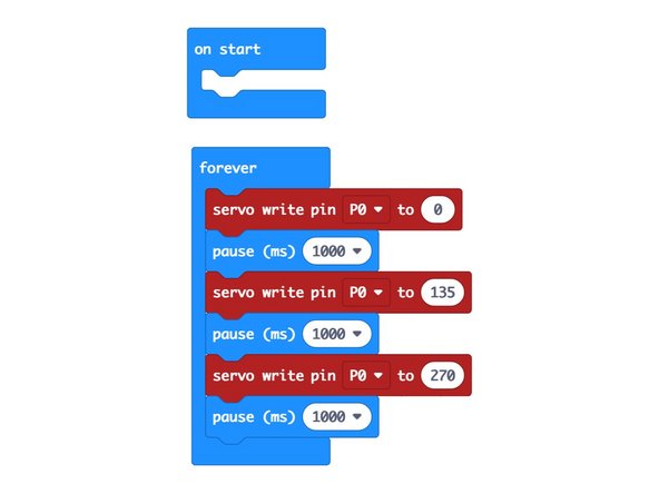
Here's our second code example, LC270 Servo 2: https://makecode.microbit.org/_0A4Va9Ai4...
-
Load this code onto your micro:bit and examine the behavior. Your servo should move to the 0 position, then close to the 210 degree position, and then to the 270 position. (Or perhaps closer to 290.)
-
While sending a value of 90 (half of 180) sets our servo to 135 (about half of 270) when we send it 135 it will really set our servo to 210 degrees. A bit confusing? Yes.
-
We're really dealing with two scales here, the value 0 to 180 that we will send to our servo, and the value 0 to 270 that our servo will move to.
-
-
-
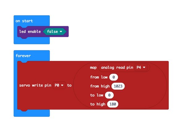
Here's our third code example, LC270 Servo 3: https://makecode.microbit.org/_aLACDE5fD...
-
Load this code onto your micro:bit and this time you'll be able to control the angle using the potentiometer.
-
You should be able to turn the potentiometer and see the LEGO beam on the servo react and move as you turn the dial.
-
We're using the map function in our code to take the input from the potentiometer (which will be between 0 and 1023) and mapping it onto a scale from 0 to 180 so we can set our servo appropriately.
-
If your servo moves the opposite direction of the potentiometer knob just remove the potentiometer from the LEGO baseplate, rotate it 180 degrees, and then put it back in place.
-
-
-
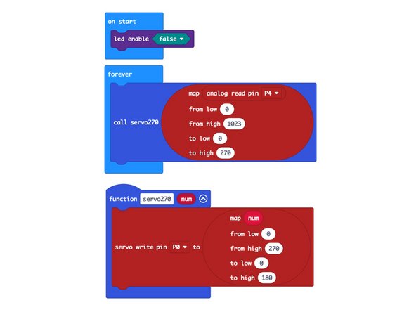
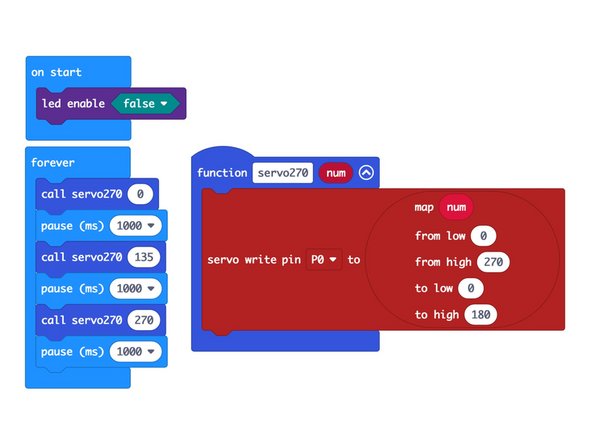
Here's our fourth code example, LC270 Servo 4: https://makecode.microbit.org/_UioEuEVag...
-
Load this code onto your micro:bit and once again you should be able to control the angle using the potentiometer.
-
We've added a function called servo270 that now allows us to call the angle of our servo on a scale from 0 to 270 and it will map that onto the 0 to 180 the servo can accept and do the right thing. (Which is, point at the correct angle.)
-
You can then call the servo270 function the same way you would use the built-in servo function, but now you can pass it a number between 0 and 270.
-
Using this function will allow the value you send to your servo, and the angle of the position to match up.
-
-
-
While we love these servos for their LEGO compatibility, getting used to the angle issue took a little time, but with this guide it should make sense and be very easy to integrate into your projects.
-
As always, if you have specific questions about this servo, or any product we carry, get in touch with us so we can assist you with more resources and guides.
-
Happy Angles!
-


Attached Documents
