Introduction
Building our Deluxe Game Show Buzzers is an advanced project and for die-hard quiz show players willing to go the extra mile!
We started with our original Game Show Buzzer System and then created a Wireless version. Both made use of our Cardboard Buttons with Maker Tape.
For this version we used 3D printed enclosures along with off-the-shelf arcade buttons for more robust slamming. We also upped our LEGO game a bit using additional bricks and flat plates for a more finished look.
Video Overview
-
-
This project is an upgraded version of our Wireless Game Show Buzzer System.
-
We swapped out the cardboard buttons and made a few minor changes to the code, and made the LEGO holding our Bit Board slightly more fancy.
-
We bought some nice arcade buttons and then designed a 3D printed enclosure for them. See the Arcade Button Enclosure guide for that portion of the build.
-
This is an advanced project that requires purchasing arcade buttons and using a 3D printer to create the cases for them to fit into.
-
-
-
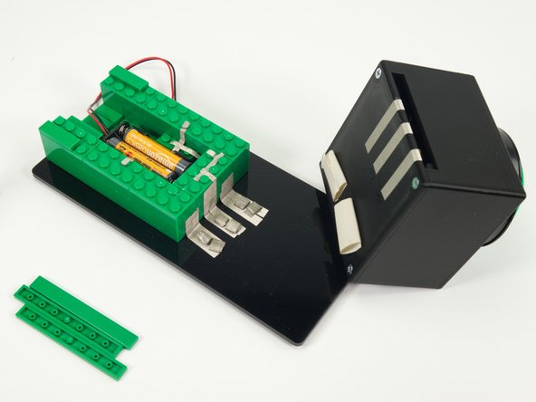
We'll start by building with LEGO bricks to create a block that will hold our Bit Board (and micro:bit) along with the Battery Pack.
-
Like any brick building project you can use all sorts of methods and parts. Use what you have! This guide will walk through what we did.
-
-
-
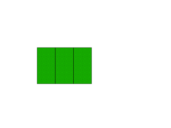
We used three 8x4 plates as our base, since it's the exact footprint of the block we'll be building. (So 12x8 will be the full size.)
-
You can use a single 16x8 baseplate if you prefer. (Our original prototype used one.)
-
-
-
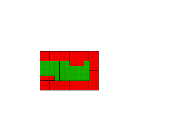
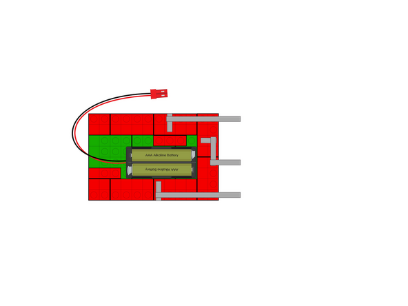
Add some 2x4 bricks along with two 1x3 bricks in the positions show in the diagram.
-
The 1x3 bricks are there to hold the Battery Pack in place, which you'll see in Step 6.
-
-
-
Add a second layer of bricks around the outside perimeter.
-
We started with two 2x2 bricks on the left side so we overlap the seams and build a more solid structure. All the rest are 2x4 bricks.
-
-
-
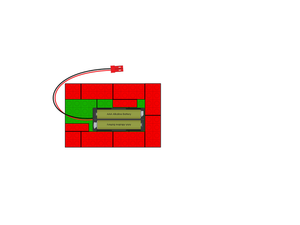
Add a 2AAA Battery Pack as shown.
-
The 1x3 bricks will prevent it from sliding around or out.
-
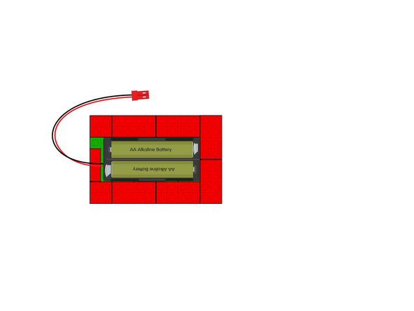
If you want to use 2AA Battery Pack just remove the 1x3 brick on the right side, and rotate the 1x3 brick on the left side and it will fit just fine!
-
-
-
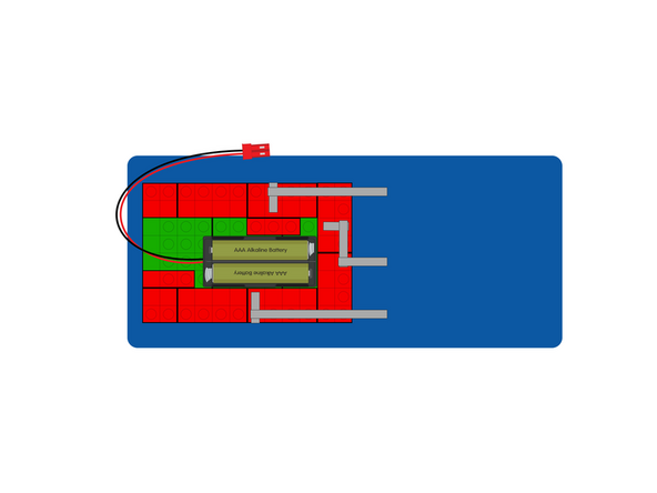
This one is a little tricky!
-
If you look at exactly where the Maker Tape is on the brick studs, the position is made to match the pins on the Bit Board we'll add in the next step.
-
We're running the Maker Tape to the right side along the top, and then down the right side wall.
-
At this point we added a base to stick the whole brick block to, and so we have something to stick the Maker Tape to.
-
We used some laser cut acrylic but you can use cardboard, wood, or even 3D print a plate. (Anything non-conductive should work.)
-
-
-
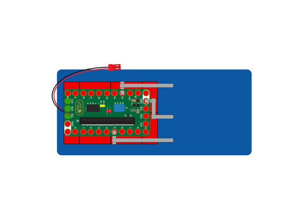
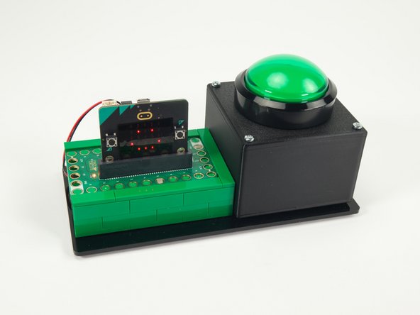
With our Maker Tape in place we can add the Bit Board.
-
Make sure you have the orientation correct, and press the Bit Board down onto the studs of the bricks.
-
-
-
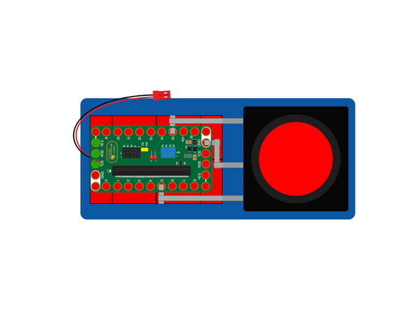
We can now add the button, and connect it using Maker Tape to the connections leading to the pins on the Bit Board.
-
The connections:
-
Pin 15 goes to the Positive side of the LED inside the button.
-
Pin 5 goes to the NO (Normally Open) connection on the microswitch inside the button.
-
Ground (GND) goes to ground on the LED and ground on the microswitch inside the button.
-
-
-
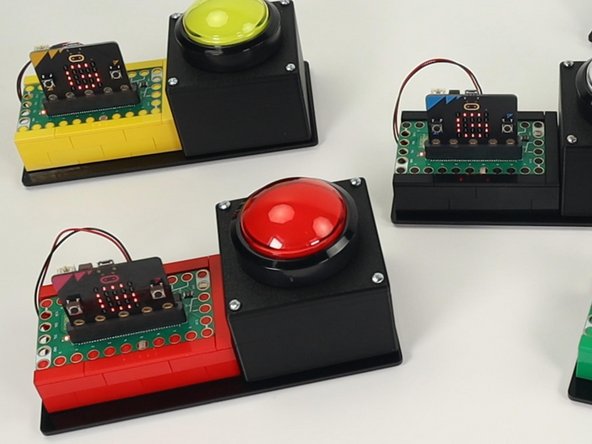
We got a little bit more fancy with our build, and added some flat bricks to the top to cover the exposed brick studs.
-
We also used Maker Tape loops to attach and connect our button.
-
There are many ways to build and make the connections, so do what works for you!
-
-
-
Once you have a set of buttons you can move on to programming them.
-
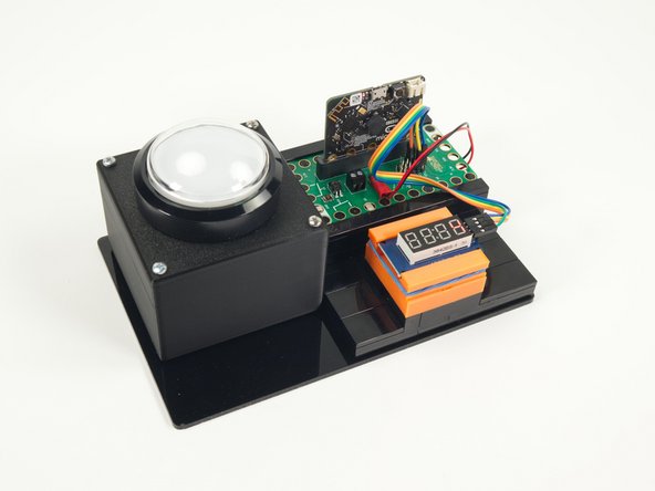
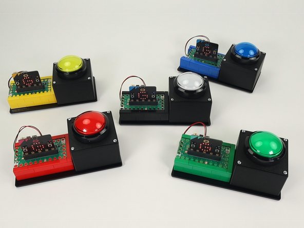
We wanted to have enough for four teams and a host, so we have five units in total, all built the same.
-
We originally set up the host controller like we did for our original wireless version, but decided the simplified version was a better option. (See second photo.)
-
-
-
If you've never used a micro:bit before you'll want to check out this guide: Bit Board V2 Setup and Use
-
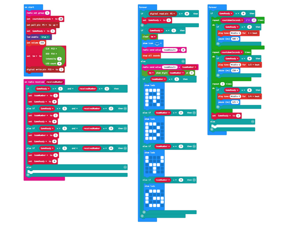
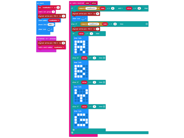
We're going to load the following code for our GSBS Deluxe Host program: https://makecode.microbit.org/_deheY17LW...
-
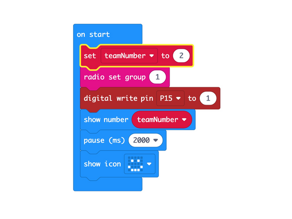
Remember that if you want to change the countdown time you just need to edit the countdownSeconds variable in the code.
-
-
-
Next we'll load the following code for our GSBS Deluxe Team program: https://makecode.microbit.org/_7tAJM3UVj...
-
Once you load the code for the Team 1 button you'll need to change the teamNumber variable to 2 and program the Team 2 button, and so on...
-
We saved four different hex files, named 1-Red.hex, 2-Blue.hex, 3-Yellow.hex, and 4-Green-hex
-
Make sure each button has a different number or they will conflict when playing the game!
-
Once you program all of the team buttons you are ready to try them out!
-
-
-
You may have noticed that while we used Team Numbers in the previous version we've moved to Team Colors for this one, so you'll see R, B, Y, G on the matrix for Red, Blue, Yellow, Green.
-
You will still see a number (1, 2, 3, or 4) on each micro:bit when you first power it on.
-
And yes, Red = 1. Blue = 2, Yellow = 3, and Green = 4.
-
The Host is the white button, and is in control of things, so no number or color is needed there.
-
-
-
We're ready to test!
-
Make sure the code is loaded onto each micro:bit and you've got power going to all the units.
-
When you press a button it should show the corresponding letter (R,B,Y, or G) on all of the Team Units.
-
You'll also hear the host unit beeping the countdown for the team to answer the question.
-
When the time is up (or the host resets the system) all units will show the smiley face again letting you know they are ready to go again.
-