Introduction
Note: V3 of our Solar Tracker is the most recent version.
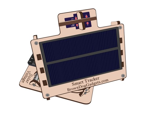
The Dual Axis Smart Tracker 2.0 is a project designed to teach engineering and programing. The project uses a custom Arduino shield and sensor holder, a custom laser body, and code. The kit includes everything you need to build the project.
If you'd like to build your own from scratch, or customize part of this project on your own, you can find our Open Source resource files here.
Our Open Source files include:
- Laser Cut Files
- PCB Design Files
- Code
Tools
Video Overview
-
-
Start by attaching one of the Servos to the center ring.
-
Use the two screws inside the Servo bag.
-
Attach the servo to the bottom, which is the side without any etching.
-
-
-
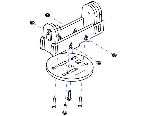
Screw each of the four legs into the center ring.
-
-
-
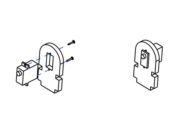
Screw the second Servo into the the mount.
-
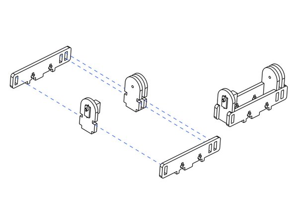
Combine the wooden parts as shown to build the center section of the tracker.
-
-
-
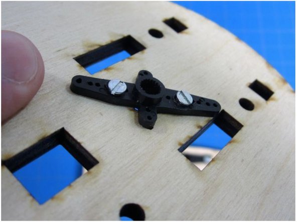
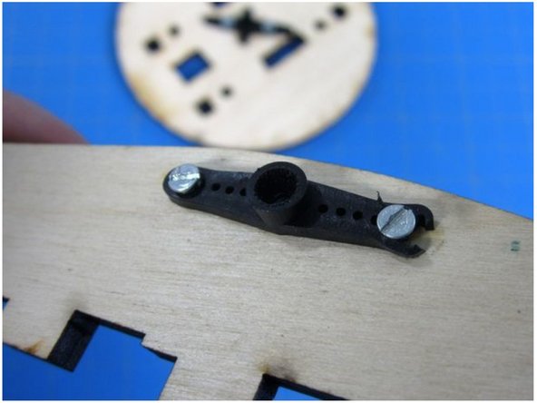
Using two of the very small screws, attach a Servo Horn to the bottom of the circular wooden piece.
-
Use either the four prong Servo Horn or two prong Servo horn.
-
Only use two screws. You need the other two for the second Servo.
-
-
-
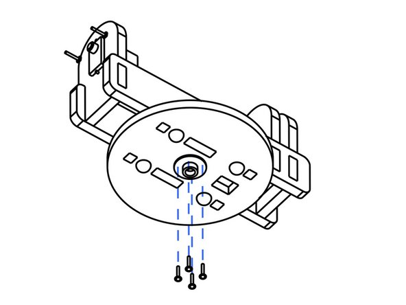
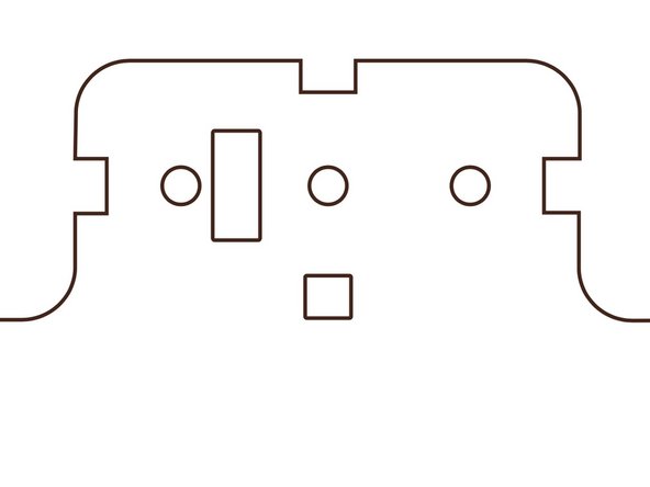
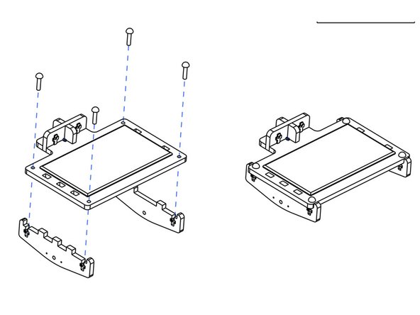
Screw the Sensor Holder into place.
-
Screw the two wooden dividers into place.
-
You'll find one 1/2 inch 8-32 screw in your kit. This goes in the center hole and is used to screw the sensor holder to the wooden head.
-
The other two holes are used to secure the two dividers to the wooden head, and use one of the many 3/4th inch 8-32 screw.
-
-
-
Use the two remaining small screws to attach a horn to the inside of one of the two triangle shaped pieces.
-
That triangle piece should go on the LEFT side of the face.
-
Attach both triangle pieces to the head.
-
-
-
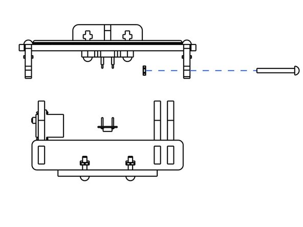
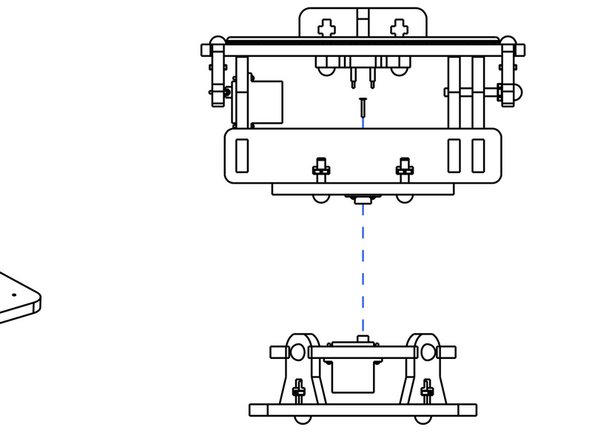
Connect the Top and Middle sections.
-
Use one of the screws found in the Servo bags to connect the Servo and Horn together.
-
-
-
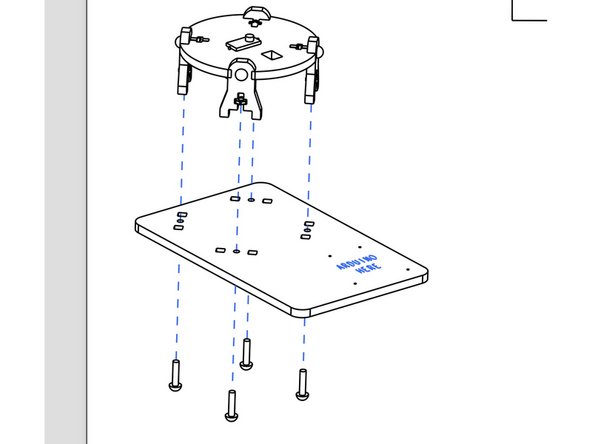
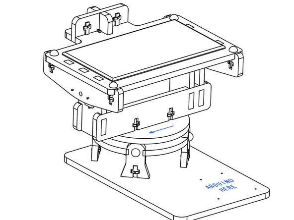
Connect the four legs to the base.
-
This would also be a good time to add the rubber feet to the bottom of the base.
-
-
-
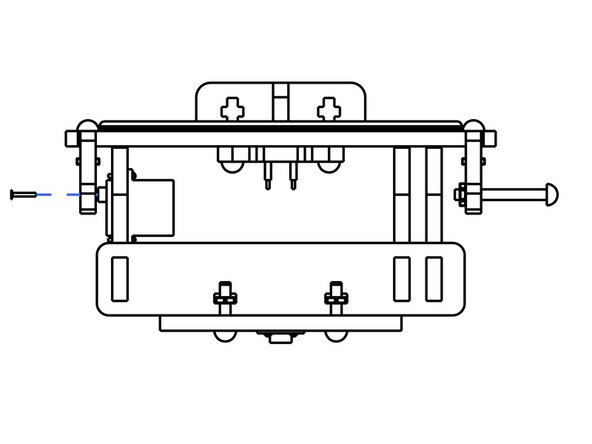
Connect the two halves.
-
Use the remaining Servo screw to hold the two halves together.
-
-
-
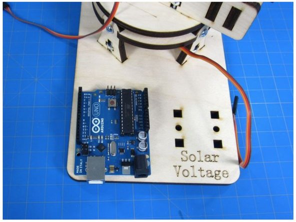
Use two of the M3 screws to screw the Arduino into the base.
-
-
-
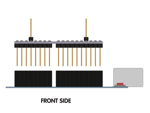
Match the pins on the Shield to the Pins on the Arduino.
-
Push into place.
-
-
-
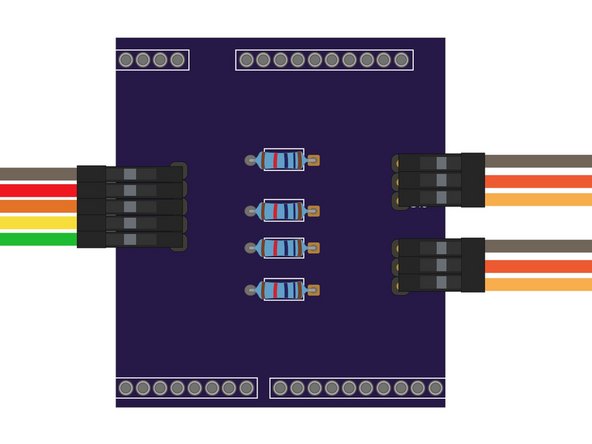
Attach the Servos to the shield. The yellow is the signal wire.
-
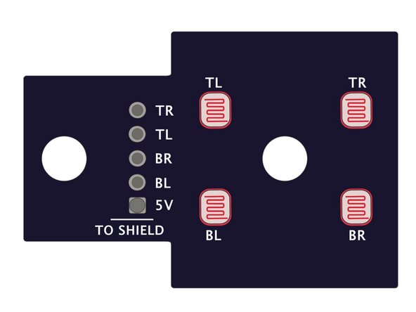
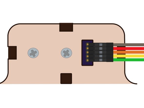
Use the Ribbon Cable to connect the back of the Sensor Holder to the Arduino Shield.
-
-
-
You'll most likely need to Zero Out the Servos before the code will work properly.
-
To Zero Out the Servos the Servos, remove the screw connecting the Servo to their individual horn. Turn the servo ENTIRELY Clockwise.
-
Place the horn back on facing forward. Screw back into place.
-
We're doing this so that the tracker body moves properly with Servo movements.
-
-
-
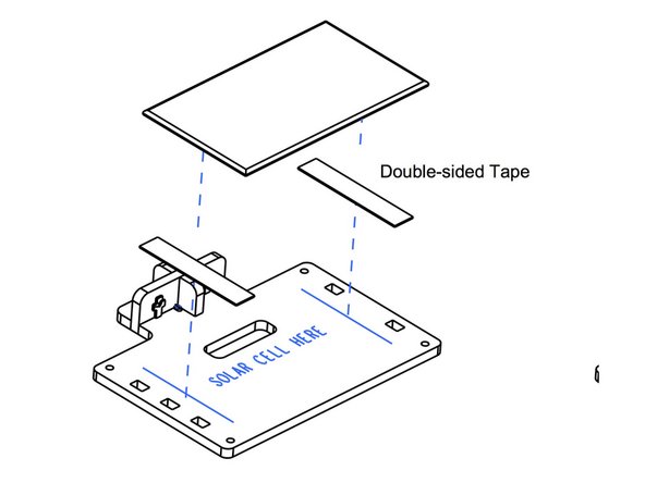
Use the included Velcro to attach the Solar Cell to the head.
-
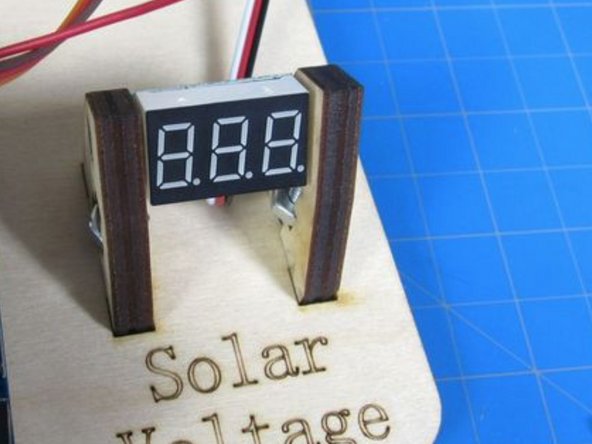
Put the Volt Meter into the two wooden holders and screw them into the base.
-
Use the Wire Nuts to connect the Solar Cell and the Volt Meter. You may need to wire strip the ends of all the wires.
-
Black wire to Black wire, Red and White Volt Meter wires to Solar Cell Red wire.
-
-
-
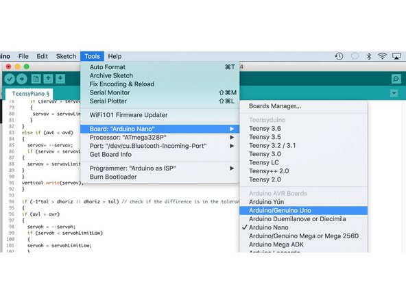
Download and open up the Arduino Software. Open up a new project window.
-
Copy and paste this code into your project window.
-
Choose Arduino Uno as the board. Upload.
-
It goes without saying that you need to plug in your Arduino to your computer as well as choose the correct port in the Arduino settings.
-
-
-
Most problems with this project revolve around getting the wooden body and the Servos to play nice together.
-
Readjusting the body a couple of times is completely normal.
-
If you're having issues with your Arduino and computer talking to each other, ask for help on our forums.
-