Introduction
Use the printable templates and this guide to assemble these fun Christmas paper-craft projects that move and light up!
Video Overview
Featured Document
-
-
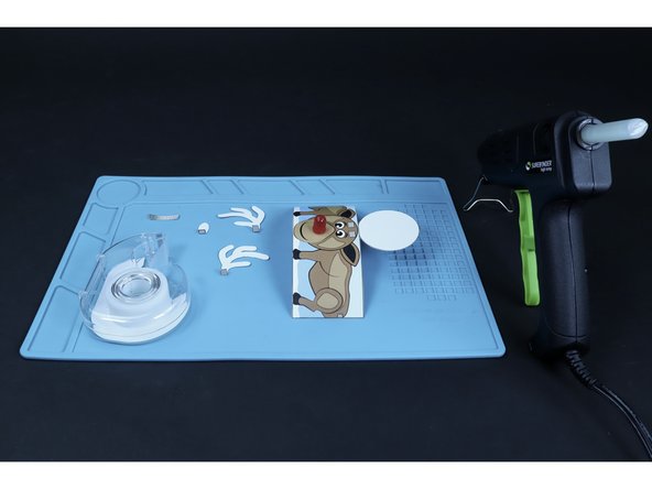
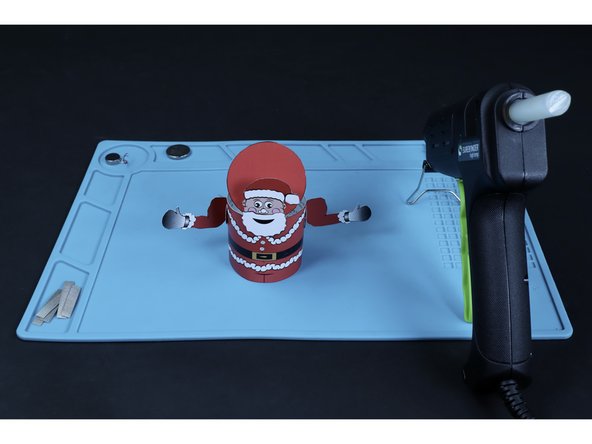
Gather your materials and tools. Note: Although both 10mm LEDs AND self-sticking vibrating motors are listed in the materials section, ONLY Rudolph the Red-Nosed Tube Deer requires BOTH parts.
-
Remember, B&W versions of these templates can be found in addition to already colored ones. The template files are at the bottom of this guide.
-
-
-
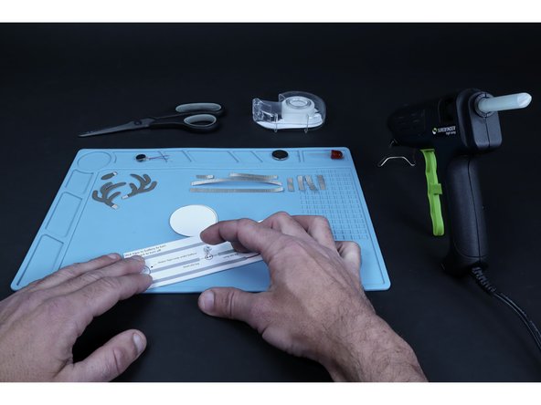
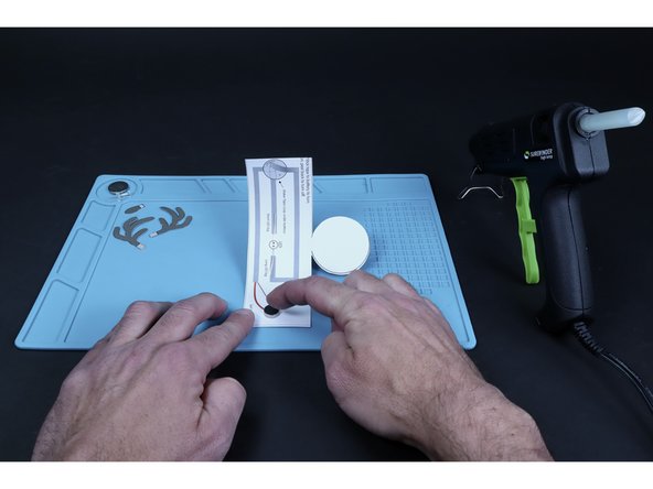
Print, cut and color your Christmas project/parts on heavy card stock. Take care to keep the circular lid attached to the rest of the body by not cutting across the portion where the two shapes meet.
-
-
-
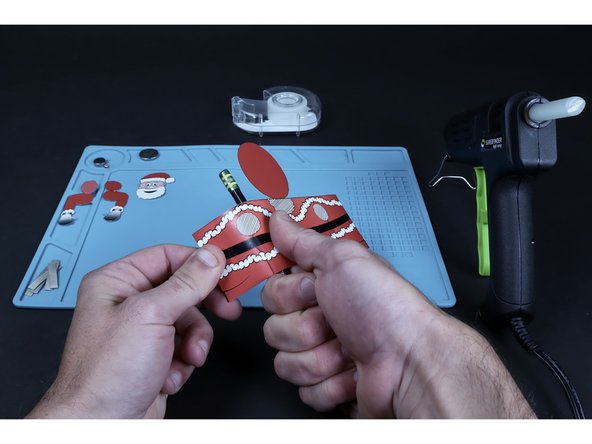
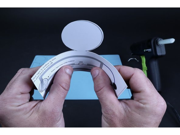
Using a pencil as shown, pull your chosen project against this round shape from straight edge to straight edge. This will give the project a curl and make it easier to turn into a tube when necessary.
-
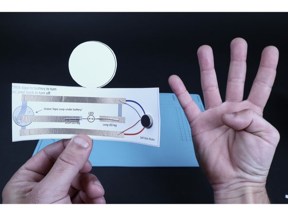
Santa's circuitry is on the underside of the lid while Rudolph's is on the inside of the tube. To make circuit assembly easier, wait until the end to join the two matching straight edges of Rudolph. If you are assembling Santa, you can use tape now to join the two matching edges and form the tube shape.
-
-
-
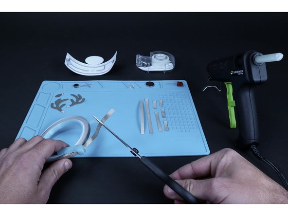
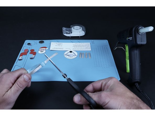
Use the circuit diagram on the back of the project to help you measure and cut the number of pieces of conductive Maker Tape required for the project you chose. Rudolph will require 8 total pieces while Santa will require only 5 (this includes 1 piece for a tape loop).
-
-
-
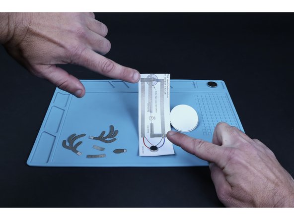
NOTE: To assemble the remainder of your Rudolph project, follow the circuit diagram on the back of your project and use Guide Steps 7-12. Skip ahead to Guide Step 13-16 for help assembling the remainder of your Santa project.
-
-
-
Using a push-pin, poke a hole for each LED leg where shown on the circuit diagram.
-
Taking care to orient the long and short LED legs as shown in both the diagram and photo 2, thread the LED through the project body from front to back.
-
Flatten the LED legs outward in opposite directions so they lay flat against the paper as shown. Now bend them slightly to match the curve that your tube now wants to be shaped as after having curled it earlier.
-
-
-
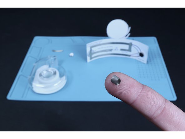
Peel and stick the vibrating motor where shown on the diagram.
-
Peel and stick the four sections of Maker Tape as shown in photo 2.
-
Peel and stick the two smaller pieces shown in photo 3.
-
-
-
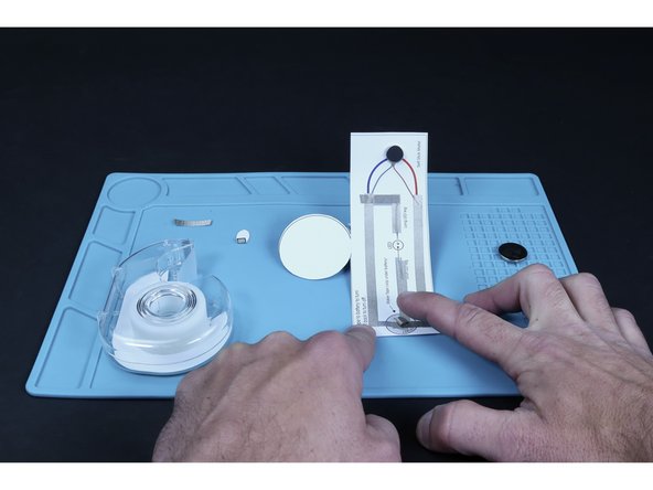
Make a tape loop out of Maker Tape and press it atop the paths that cross the battery graphic on the diagram.
-
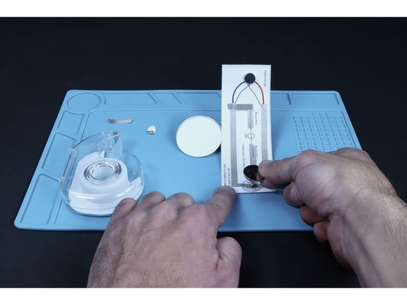
Press the battery atop that tape loop so that the positive (+) side faces UP.
-
-
-
Fold the ends of the antlers and tail as shown where the striped portion meets the non-striped.
-
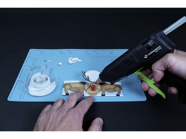
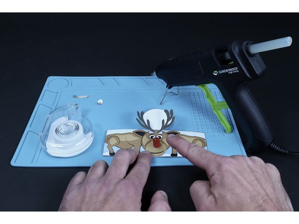
Glue the two antlers in place as pictured by applying a dot of hot glue to the striped areas on the tube body and pressing the folded, striped parts of the antlers to those areas.
-
-
-
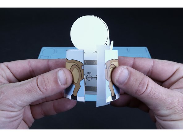
Use a piece of transparent tape to now join the two matching edges together to form the tube shape.
-
Note: You may need to continue shaping the two legs of the LED to match the curve so that when you join the two sides together, they do not want to pull the Maker Tape out of position.
-
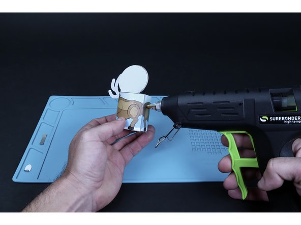
Add a final dot of hot glue to the striped area for the tail and press the striped part of the tail into place.
-
-
-
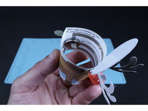
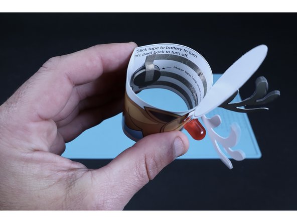
Peel and stick the final piece of Maker Tape to the top of the battery as shown.
-
Stick the end of that piece to tape path immediately above it when viewing the project upright.
-
Connecting this final piece should turn your circuit on, while peeling it back from the battery will turn your project off.
-
-
-
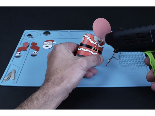
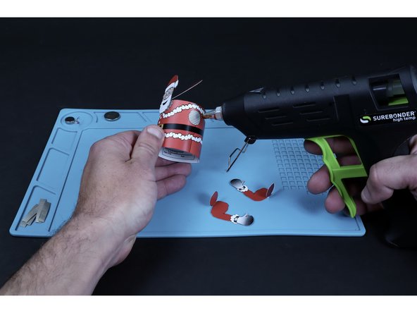
Apply hot glue to the striped area shaped liked Santa's beard. Press the matching portion of Santa's head into place.
-
Do the same for each of Santa's arms (It may be helpful to fold the connector circles and line them up with the tube body first).
-
-
-
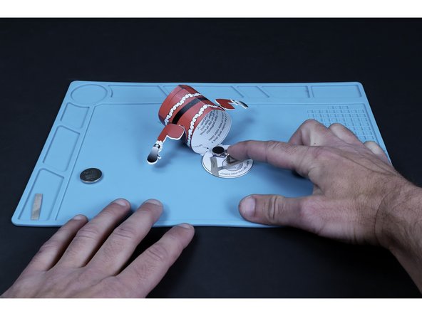
Peel and stick the vibrating motor in place where shown on the circuit diagram.
-
Peel and stick the three Maker Tape paths shown in photo 2.
-
-
-
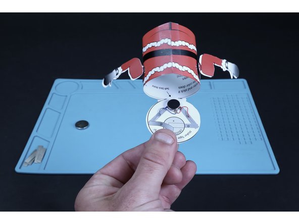
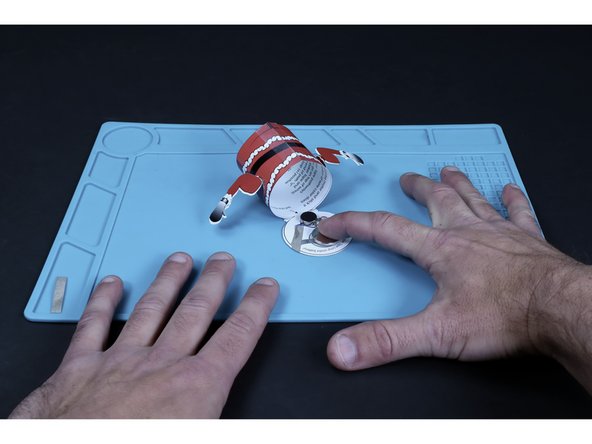
Make a tape loop out of Maker Tape and press it atop the path that crosses the battery graphic on the diagram.
-
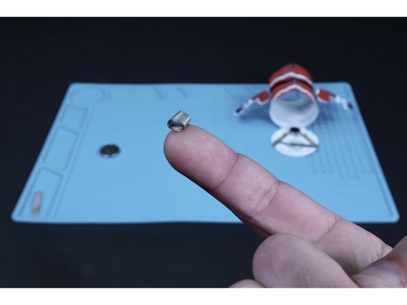
Press the battery atop that tape loop so that the positive (+) side faces UP.
-
-
-
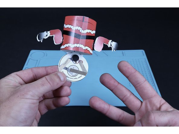
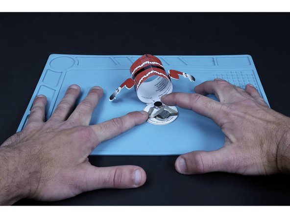
Press the final piece of Maker Tape into place as shown.
-
When in contact with the battery, your project will turn on. Peel it back to turn your project off.
-
-
-
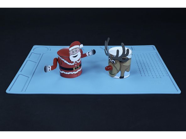
Behold...your finished creations!
-